
Shift control device for automatic transmission

A technology of automatic transmission and control device, applied in transmission control, components with teeth, climate sustainability, etc., can solve problems such as deterioration of running performance, and achieve the effect of improving speed change tolerance and preventing deterioration of running performance.

Active Publication Date: 2013-03-27
JATCO LTD +1
View PDF3 Cites 0 Cited by
  • Summary
  • Abstract
  • Description
  • Claims
  • Application Information

AI Technical Summary

Problems solved by technology

Therefore, even if the shift determined by the shift judgment is a shift that does not generate a large amount of heat and does not reach the friction element damage temperature even if the shift is performed, the shift is uniformly prohibited, so that the running performance deteriorates.

Method used


Image

  • Shift control device for automatic transmission
  • Shift control device for automatic transmission
  • Shift control device for automatic transmission

Examples


Embodiment Construction

[0053] Embodiments of the present invention will be described in detail below with reference to the drawings and the like.

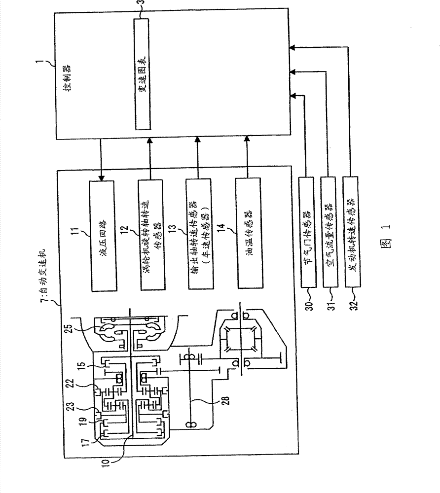
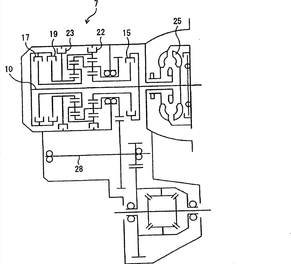
[0054] figure 1 It is a functional block diagram showing the structure of the shift control device of the automatic transmission of this embodiment. figure 2 It is a block diagram showing the structure of an automatic transmission. Such as figure 1As shown, the transmission control device is configured to include: a controller 1, an input shaft rotational speed sensor (turbine shaft rotational speed sensor) 12 for detecting the rotational speed NT of the turbine 25 and the turbine shaft 10, and an output shaft rotational speed sensor for detecting the rotational speed No of the output shaft 28. (vehicle speed sensor) 13, an oil temperature sensor 14 that detects the temperature of ATF (automatic transmission fluid), a throttle sensor 30 that detects the throttle opening of an engine not shown in the figure, an air flow sensor 31 that detects the amoun...


PUM


Abstract

An automatic transmission calculates a current thermal load state of the frictional element, predicts (S41), prior to the start of the shift, a heat generation amount of the frictional element during the shift, predicts (S42) a thermal load state of the frictional element upon shift completion on the basis of the current thermal load state of the frictional element and the predicted heat generation amount, determines (S43, S44, S45) whether to permit or prohibit the shift on the basis of the predicted thermal load state upon shift completion, and halts the determination as to whether to permit or prohibit the shift, made on the basis of the predicted thermal load state upon shift completion, when a shift mode of the shift is a second shift mode in which the heat generation amount is smaller than that of a first shift mode.

Description

technical field [0001] The invention relates to a shift control device of an automatic transmission. Background technique [0002] Generally, as an automatic transmission for automobiles, it is known that the rotation of the engine is input through a torque converter, the speed is changed by a transmission mechanism having multiple sets of planetary gears, and the rotation is output to a drive shaft or propeller shaft (axle side). [0003] The transmission mechanism of this automatic transmission transmits the rotation of the input shaft (drive shaft) to a specific gear or carrier constituting the planetary gear, or transmits the rotation of a specific gear or carrier to an appropriate output shaft according to the shift position, thereby Implement variable speed. In order to properly restrict the rotation of a specific gear or carrier during gear shifting, a plurality of friction elements such as clutches and brakes are provided, and the transmission path is switched throu...

Claims


Application Information

Patent Timeline
Patent Type & Authority Patents(China)
IPC IPC(8): F16H61/00
CPCY02T10/60
Inventor 池田知正川上大树
Owner JATCO LTD
Learn More