
Soya-bean milk making device
A technology for a soymilk machine and a container, which is applied in the field of soymilk machine, can solve the problems of complex structure and no application of cooking utensils, etc., and achieve the effects of large heating area, simple and reasonable structure, and large heat flow.
- Summary
- Abstract
- Description
- Claims
- Application Information
AI Technical Summary
Problems solved by technology
Method used
Image

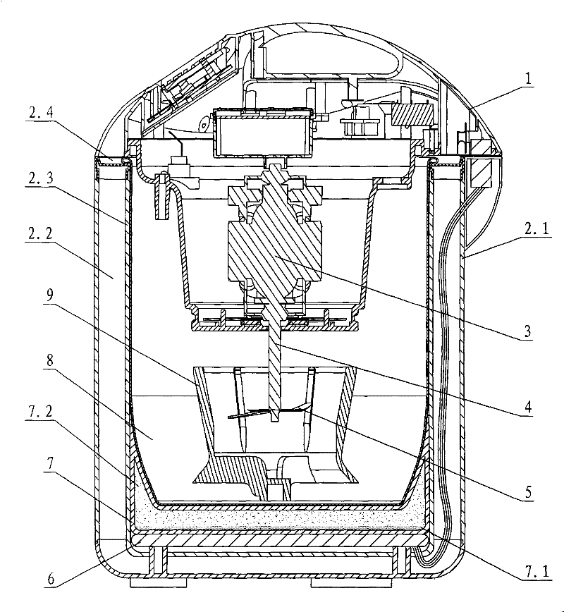
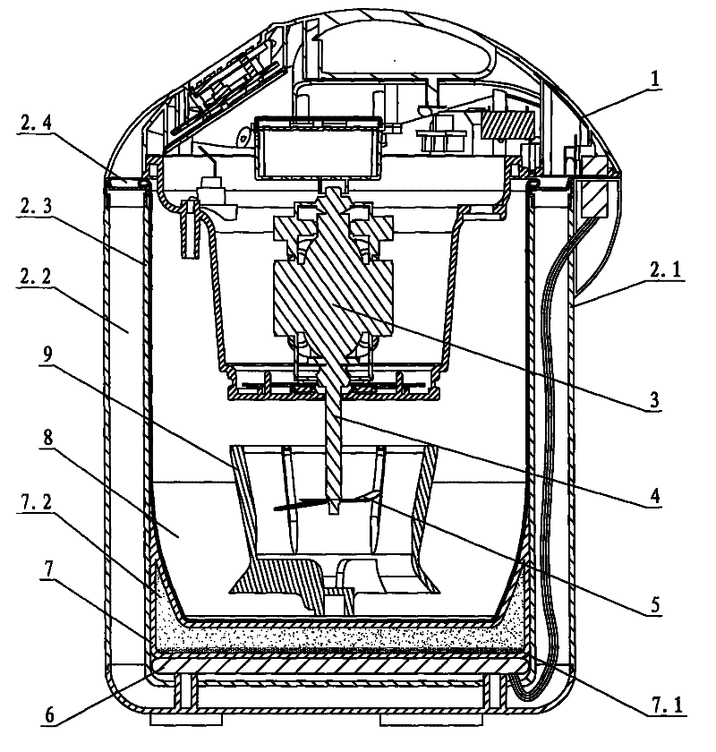
Examples
Embodiment Construction
[0013] Below in conjunction with accompanying drawing and embodiment the utility model is described further.
[0014] see figure 1 , The soybean milk machine includes a container 8 and a heating plate 6, an outer barrel is arranged outside the container, and the outer barrel and the container are separately arranged. The outer barrel has a double-layer structure, the outer layer is the outer shell 2.1, the inner layer is the reflective layer 2.3, a heat insulation cavity 2.2 is formed between the outer shell and the reflective layer, the top surface of the outer barrel is provided with a drainage groove 2.4, and the outer wall of the outer barrel is provided with The water collection box (not shown in the figure) communicates with the drain tank.
[0015] The heating plate 6 is arranged on the inner bottom of the reflective layer 2.3, and a groove-shaped superconductor is connected to the heating surface, so as to heat the container 8 through the superconductor. The superhea...
PUM
 Abstract
Description
Claims
Application Information