Bumper beam for vehicles

A technology for buffer beams and vehicles, which is applied to vehicle components, vehicle safety arrangements, bumpers, etc., can solve the problem that the buffer beams cannot effectively absorb impact energy.

Inactive Publication Date: 2009-06-17
HYUNDAI MOTOR CO LTD +1
View PDF0 Cites 8 Cited by
  • Summary
  • Abstract
  • Description
  • Claims
  • Application Information

AI Technical Summary

Problems solved by technology

In this case, the bumper beam cannot effectively absorb the impact energy

Method used


Image

  • Bumper beam for vehicles
  • Bumper beam for vehicles
  • Bumper beam for vehicles

Examples


Embodiment Construction

[0019] Reference will now be made in detail to various embodiments of the invention, examples of which are illustrated in the accompanying drawings and described below. While the invention will be described in conjunction with exemplary embodiments, it will be understood that present description is not intended to limit the invention to those exemplary embodiments. On the contrary, the invention is intended to cover not only the exemplary embodiments, but also various alternatives, modifications, equivalents and other embodiments, which may be included within the spirit and scope of the invention as defined by the appended claims.

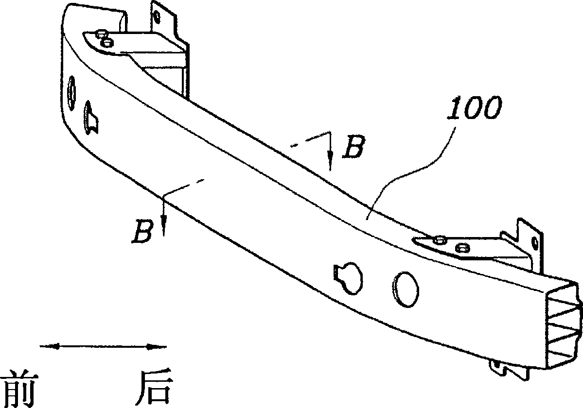
[0020] A bumper beam is provided in each of front and rear bumpers of a vehicle to absorb impact energy generated in a collision of the vehicle. An exemplary embodiment of the present invention will be described on the basis of a bumper beam provided in a front bumper of a vehicle.

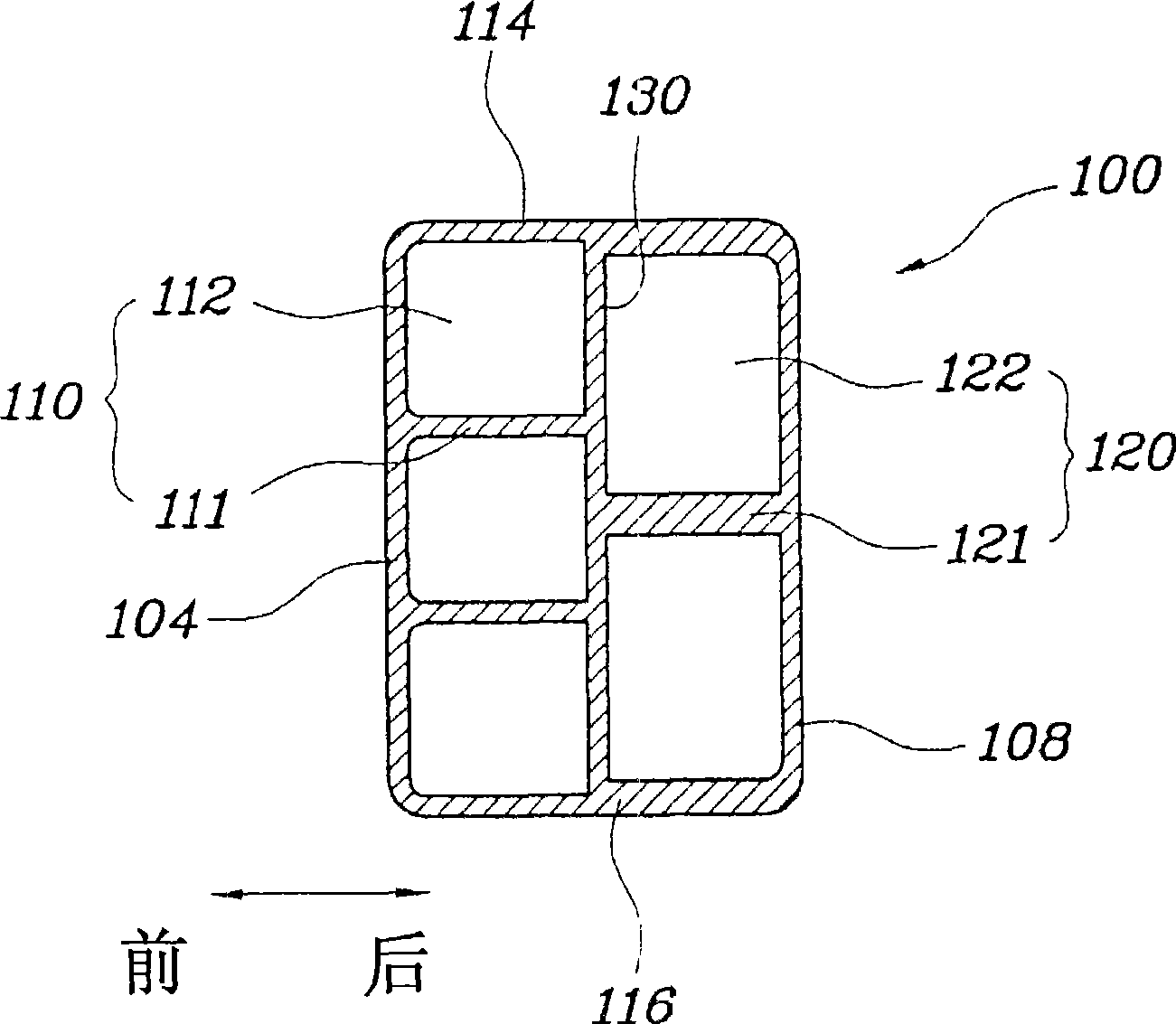
[0021] Such as figure 1 and 2 As shown, a bumper beam 100 havi...


PUM


Abstract

A bumper beam provided in a bumper for vehicles is disclosed. The bumper beam of the present invention includes a vertical rib, which sections a space in the bumper beam into several spaces in a vertical direction, and horizontal ribs, which section the space in the bumper beam into several spaces in horizontal directions. The horizontal rib that is disposed behind the vertical rib is thicker than the horizontal rib that is disposed ahead of the vertical rib. Therefore, the bumper beam can impact energy in a consecutive impact absorbing manner.

Description

[0001] Cross References to Related Applications [0002] This application claims priority from Korean Application No. 10-2007-0130543 filed on December 13, 2007, the entire contents of which are hereby incorporated by reference. technical field [0001] The present invention relates to a bumper beam provided in a vehicle bumper for absorbing impact. Background technique [0002] As is known to those skilled in the art, bumpers are provided on vehicles with elastic impact absorbing capabilities to absorb and dissipate the impact energy generated in the event of a vehicle collision. Such a bumper is provided on each of the front and rear ends of the vehicle. The bumper includes a bumper skin that determines the appearance of each of front and rear ends of the vehicle, and a bumper beam provided inside the bumper skin to absorb external impact energy. [0003] A conventional bumper beam includes a plurality of ribs that absorb impact energy through a structure that deforms wh...

Claims


Application Information

Patent Timeline
Patent Type & Authority Applications(China)
IPC IPC(8): B60R19/18
CPCB60R19/18B60R2019/182B60R19/023B60R19/03B62D21/152B60R2019/1813B60R2019/186B60R2019/1893
Inventor 辛镕硕
Owner HYUNDAI MOTOR CO LTD
Why Eureka
Try Eureka