Internal combustion engine

A technology for internal combustion engines and gears, applied in mechanical equipment, engine control, machines/engines, etc., can solve the problems of increasing the axial width of gears and high detection sensitivity, and achieve the effect of suppressing large-scale

Active Publication Date: 2009-07-01
HONDA MOTOR CO LTD
View PDF1 Cites 10 Cited by
  • Summary
  • Abstract
  • Description
  • Claims
  • Application Information

AI Technical Summary

Problems solved by technology

[0004] However, in the conventional structure, since the rotation sensor is provided on the gear that moves in the axial direction of the transmission, it is necessary to increase

Method used


Image

  • Internal combustion engine
  • Internal combustion engine
  • Internal combustion engine

Examples


Embodiment Construction

[0045] Next, an embodiment of the present invention will be described with reference to the drawings.

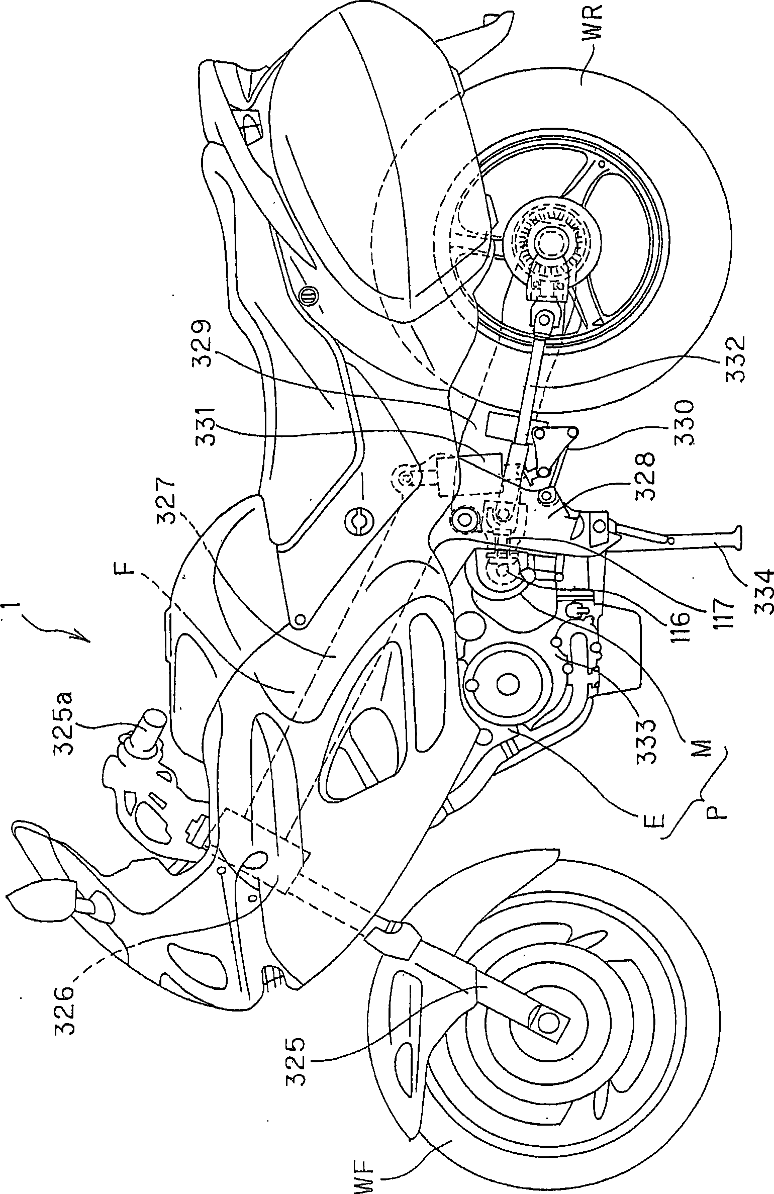
[0046] figure 1 It is the left side view of the motorcycle.

[0047] exist figure 1Among them, the symbol F represents the frame of the motorcycle 1, and the frame F has a head pipe 326, a pair of left and right main frames 327, 327, and a pair of left and right pivot plates 328, 328; The front fork 325 that pivotally supports the front wheel WF is supported; the pair of left and right main frames 327, 327 extend backward and downward from the head pipe 326; the pair of left and right pivot plates 328, 328 are connected to the two main frames 327 , 327 extends downward from the rear; pivot plates 328, 328 swingably support the front end of the rocker arm 329, and the rear wheel WR is supported on the rear portion of the rocker arm 329. Symbol 325a is steering handle. A connecting rod 330 is arranged between the lower part of the pivot plate 328 and the front part of the ...


PUM


Abstract

The invention relates to an internal combustion engine, which harbors a crankshaft and a transmission in a crank case; wherein the transmission is provided with a plurality of gears for gear shift; furthermore, the transmission is provided with an input shaft for inputting the rotary power of an input crankshaft and an output shaft for transmitting the rotary power of the crankshaft through the gear from the input shaft and further transmitting the rotary power to a driving wheel. Rotation detection devices (401, 402) for detecting the rotating speed of the transmission and the gears (49c, 49d) with fixed axial position which are linked with the input shaft (28) oppositely configure detection parts (401a, 402a) of the rotation detection devices. Hence, the internal combustion engine with the rotation detection devices can detect the rotating speed of the transmission gear without increasing the axial width dimension of the gear, applying expensive sensors with high detection sensitivity or restricting the degree of freedom of the configuration of a variable-speed drum.

Description

technical field [0001] The present invention relates to an internal combustion engine having a rotation detection device for detecting the rotational speed of a gear of a transmission. Background technique [0002] Such a rotation detection device is known (for example, refer to Patent Document 1). A transmission having a plurality of gears (rotating bodies) on the shaft is provided behind the crankcase, and the rotation detection device moves axially with one of the plurality of gears of the transmission. A rotation sensor is correspondingly provided for the gear, and the rotation sensor detects the rotation speed of the gear, thereby detecting the rotation speed of the shaft of the transmission. [0003] [Patent Document 1] Japanese Patent Laid-Open No. 2000-87780 [0004] However, in the conventional structure, since the rotation sensor is provided on the gear that moves in the axial direction of the transmission, it is necessary to increase the axial width dimension of ...

Claims


Application Information

Patent Timeline
IPC IPC(8): F02D35/00B62J99/00F02B61/02F16H57/02F16H57/023F16H57/028F16H57/029F16H57/03
Inventor 藤本靖司小岛浩孝菅野嘉久
Owner HONDA MOTOR CO LTD
Why Eureka
Try Eureka