
Robot for mounting anti-detour lightning lightning rod on high-tension line

An anti-shielding and lightning rod technology, applied in the field of robotics, can solve problems such as difficulties in upper and lower high-voltage line towers, loose wire clips, and affecting lightning protection effects

Inactive Publication Date: 2010-10-06
武汉水院电气有限责任公司
View PDF3 Cites 0 Cited by
  • Summary
  • Abstract
  • Description
  • Claims
  • Application Information

AI Technical Summary

Problems solved by technology

There are two problems with this installation method: one is that it is very dangerous. Due to the heavy weight of the flying car, it is not only difficult to go up and down the tower pole of the high-voltage line, but also rust and aging will occur in the part of the lightning protection line that has been struck by lightning many times, and its strength will be reduced. If the lightning protection Second, the cost is high, not only the manufacturing cost of the flying car itself is high, but also the cost of installing the flying car every time it is used is also high, exceeding the price of the anti-shielding lightning rod itself
Although the installation method of this lightning rod is relatively simple, due to the limited clamping force of the prestressed spring, especially after a long period of exposure to the sun, wind and rain, thermal expansion and contraction, spring corrosion and stress fatigue, the spring's elasticity will decrease. , causing the wire clamp to loosen, the lightning rod is not fixed tightly and slides on the lightning wire, which affects the lightning protection effect

Method used


Image

  • Robot for mounting anti-detour lightning lightning rod on high-tension line
  • Robot for mounting anti-detour lightning lightning rod on high-tension line
  • Robot for mounting anti-detour lightning lightning rod on high-tension line

Examples


Embodiment Construction

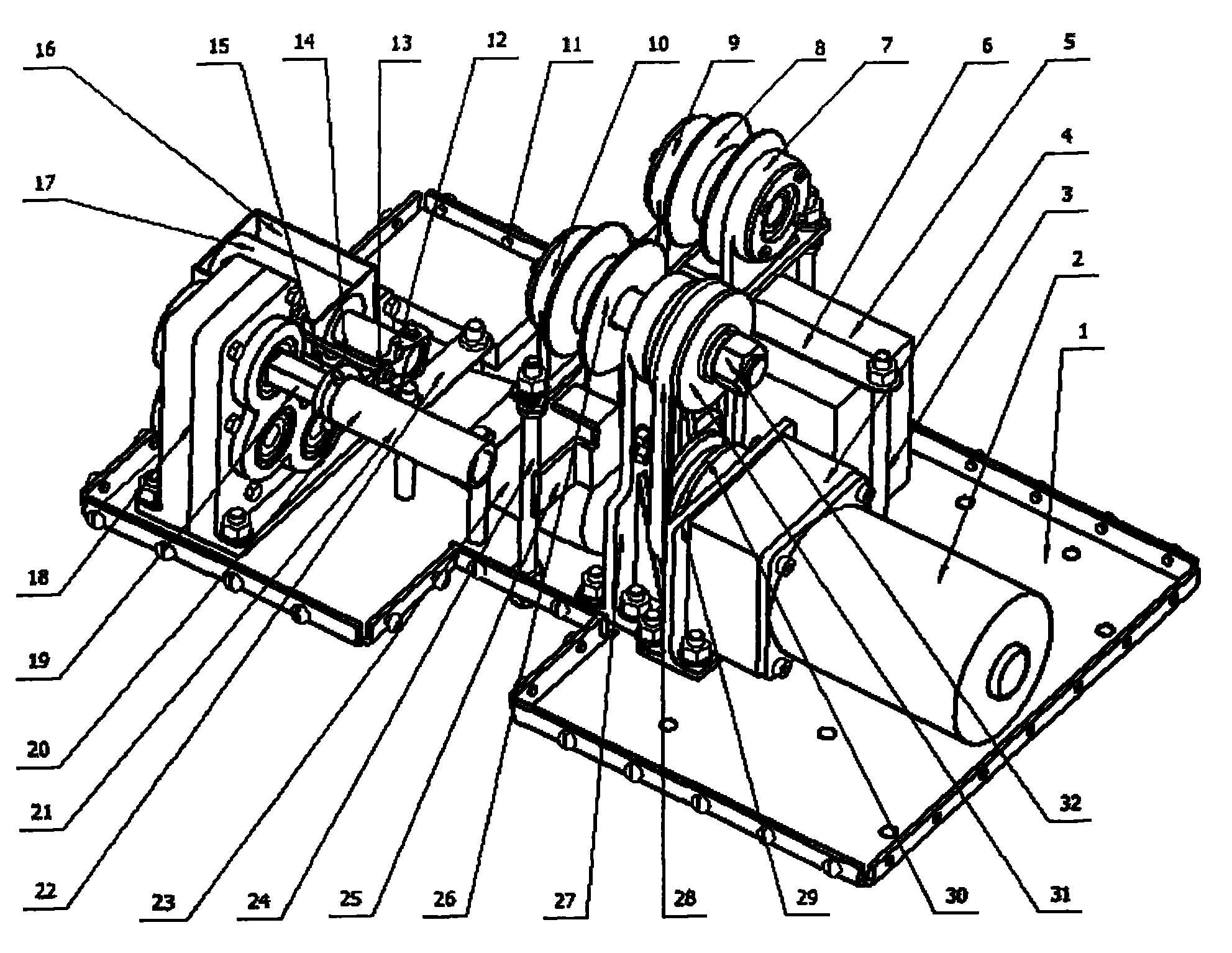
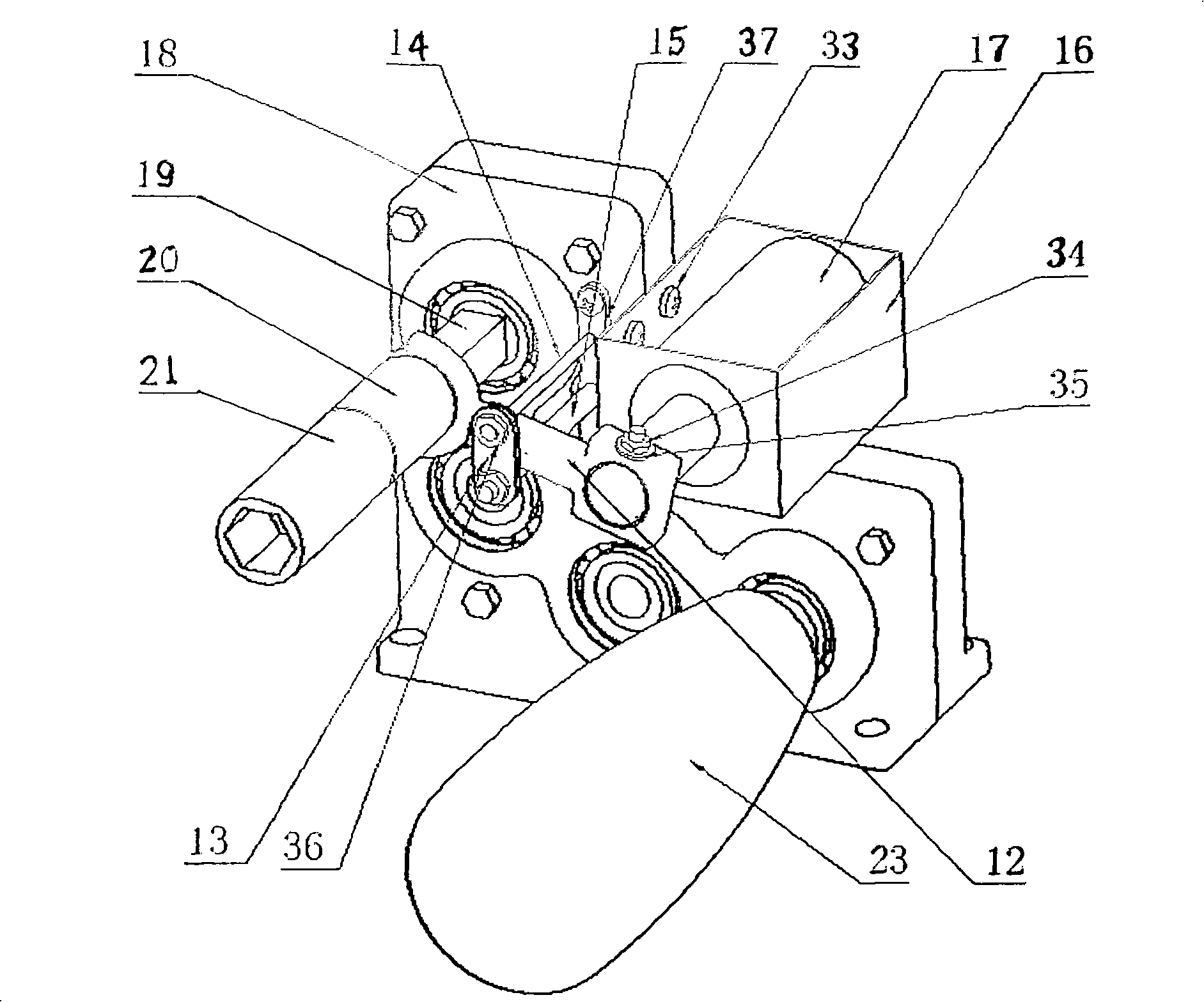
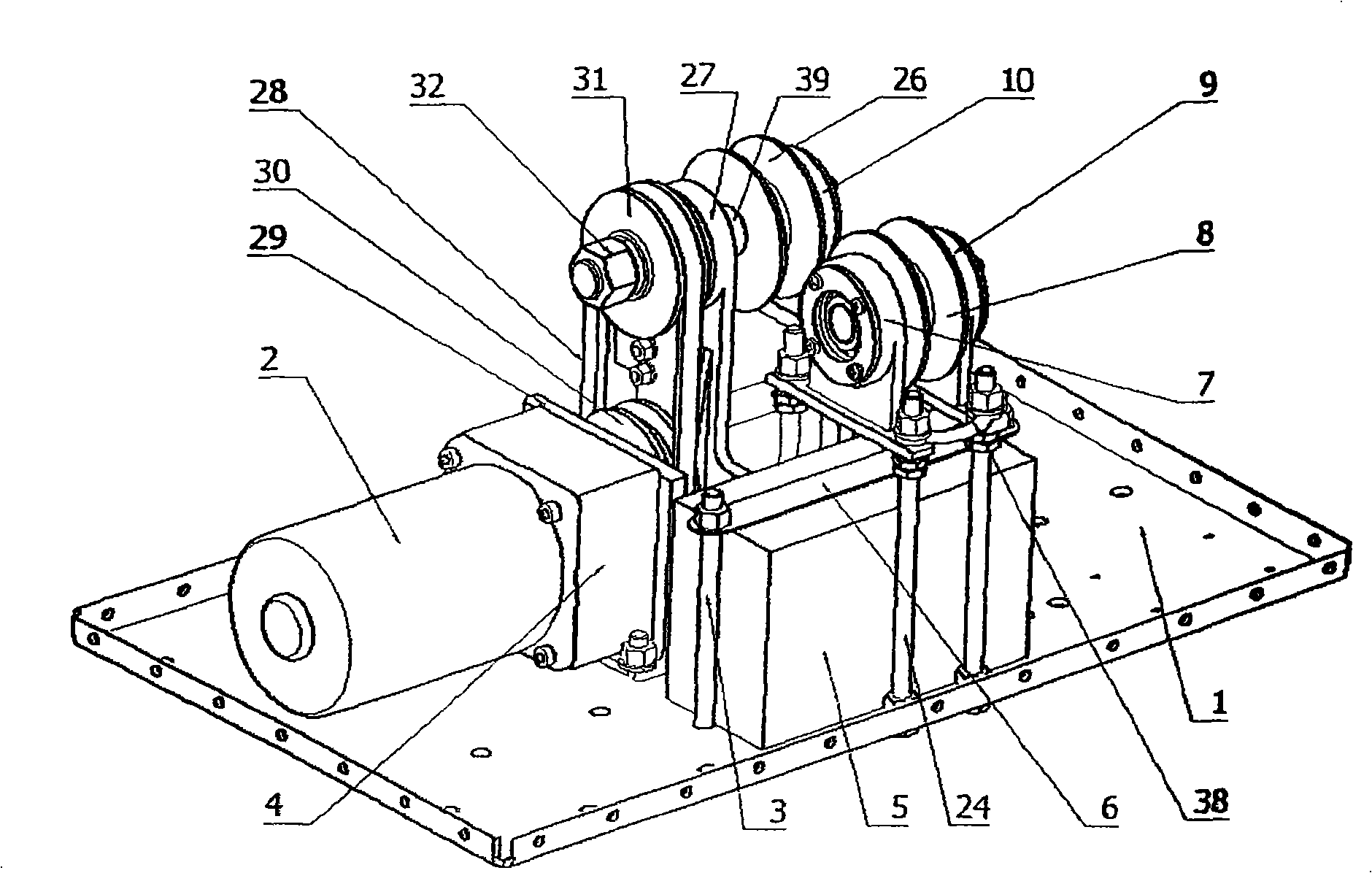
[0021] refer to figure 1 , 2 , 3. The present invention consists of a chassis, a traveling mechanism A, a flexible working mechanism B and a wireless control system C. The case cover is connected with the base plate 1 by screws 11 to form a case. The traveling mechanism A, the flexible working mechanism B and the wireless control system C are installed in the case, which can effectively prevent the main parts from being damaged by external force. The battery pressure strip 6 is fixed on the bottom plate 1 by fixing bolts 3 . The electromagnet 17 is installed on the electromagnet mounting base 16, and the electromagnet mounting base 16 is installed on the gear box 18 through the screw 33. The motor 2 is mounted on the base plate 1 through a motor base 29 . The case cover and the base plate are connected by connecting screws 11.

[0022] The battery 5 of the running mechanism A drives the motor 2, and the motor 2 drives the driving wheel 26 and the balance wheel 8 through t...


PUM


Abstract

The invention discloses a robot for mounting a lighting rod for lighting shielding failure prevention for a high-voltage wire and relates to a robot for mounting a lighting rod for lighting shielding failure prevention for use in a high-voltage transmission line in the power industry. The robot consists of a machine case, a traveling mechanism A, a flexible working mechanism B and a wireless control system C, wherein the traveling mechanism consists of a battery, an electric motor, a reducing box, a transmission mechanism, a driving wheel and a balance wheel, the flexible working mechanism B comprises an electromagnetic iron, a shift fork, an electric torque wrench, a gear box, a universal joint, a sleeve and the like, and the wireless control system C comprises a remote controller, a remote switch, an electromagnetic relay and the like. All mechanisms are arranged in the machine case. The manually operated wireless remote controller controls the robot to move forward on a lighting wire, send the lighting rod to a preset position and stop, automatically fasten a locking bolt of the lighting rod for mounting the lighting rod on the lighting wire, separate from the locking bolt, andfinally return. The robot can mount the lighting rod by fastening a wire clamp with the bolt for people and has the advantages of firm and reliable mounting, looseness prevention and safe and reliable use.

Description

technical field [0001] The invention relates to a robot used for installing anti-shielding lightning rods on high-voltage transmission lines in the electric power industry. Background technique [0002] In the power industry, although lightning protection lines are installed on high-voltage transmission lines, the power grid tripping and power outage accidents caused by lightning strikes have always been ranked first in power grid tripping and power outage accidents caused by various accidental factors. Especially in the vicinity of high-voltage line towers in some high-voltage transmission line sections, frequent lightning strikes in thunderstorm seasons cause power grid tripping and blackout accidents, which are all caused by lightning shielding. [0003] In the past two years, there have been several high-voltage line anti-shielding lightning rod products on the market, and their installation methods are different. Some are clamped by prestressed springs, and some are lo...

Claims


Application Information

Patent Timeline
Patent Type & Authority Patents(China)
IPC IPC(8): B25J1/00H02G13/00H02K7/10
Inventor 冯霞李天昌李恩志周文俊邱凌
Owner 武汉水院电气有限责任公司
Learn More