Electroluminescent lamp membrane switch

A membrane switch, light-emitting lamp technology, applied in the direction of electrical switches, electrical components, legends, etc., can solve the problems of contamination of transparent conductive layers, electrical connection interference, etc., and achieve the effect of reducing the total thickness, production cost and processing time.

Active Publication Date: 2009-07-22
2461729 ONTARIO
View PDF3 Cites 5 Cited by
  • Summary
  • Abstract
  • Description
  • Claims
  • Application Information

AI Technical Summary

Problems solved by technology

This is because the patterned layer interferes with the electrical connection of the often used ITO conductive layer on th

Method used


Image

  • Electroluminescent lamp membrane switch
  • Electroluminescent lamp membrane switch
  • Electroluminescent lamp membrane switch

Examples


Example Embodiment

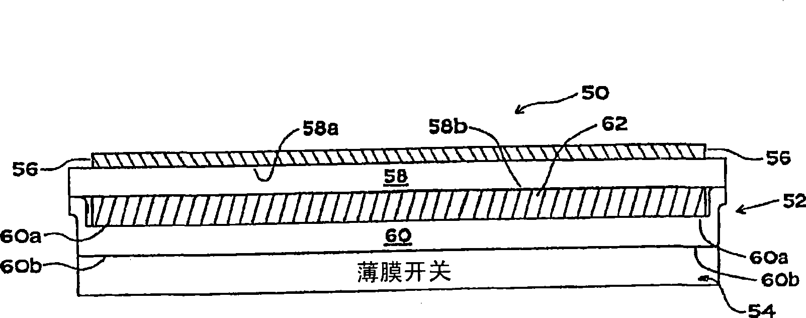
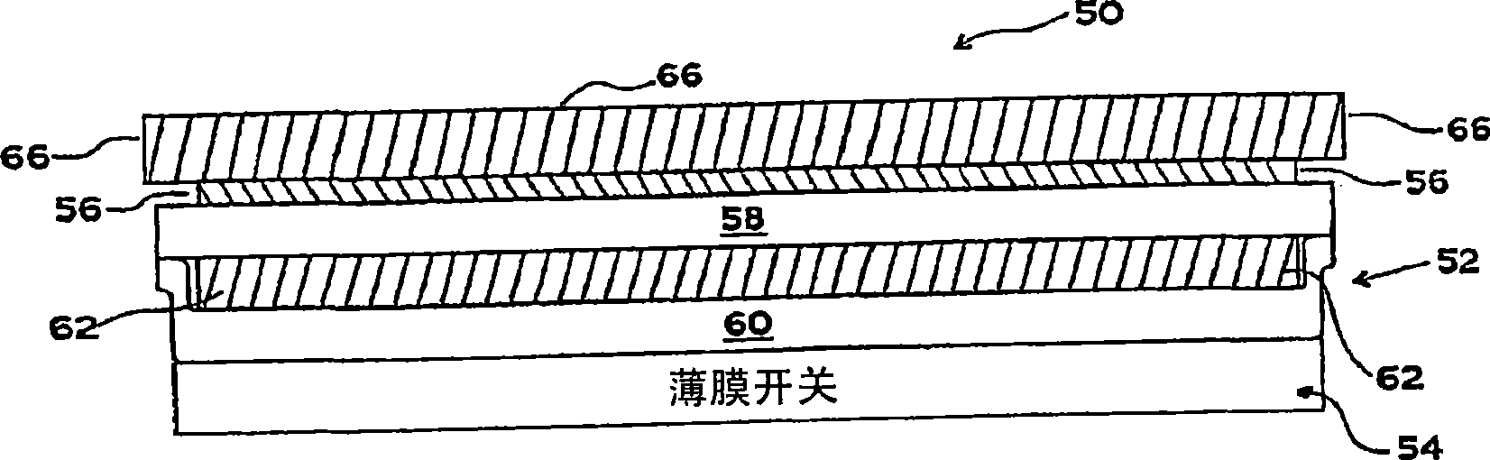
[0038] refer to figure 2 , which shows a continuous printed EL lamp membrane switch assembly of the present invention, generally identified by the reference numeral 50 . The switch 50 includes an electroluminescent lamp membrane system, generally identified at 52 , a membrane switch, generally identified at 54 , and a graphic layer 56 . The lamp system 52 includes a top insulating layer 58 and a bottom insulating layer 60 . The top layer 58 has a front surface 58a and a rear surface 58b. The bottom insulating layer 60 includes a front surface 60a and a rear surface 60b. An electroluminescent lamp 62 is disposed between insulating layers 58 and 60 . lamp 62 included next will refer to Figure 8 Each layer is described. For example, lamp 62 may comprise an electroluminescent lamp as shown and described in US Patent No. 5,856,030, the relevant disclosure and drawings of which are incorporated herein by reference.

[0039] The top insulating layer 58 of the light system 52 i...


PUM


Abstract

A combined monolithic electroluminescent lamp (52) and membrane switch (50) is manufactured by continuous printing. Graphic indicia (56) are imprinted on a deformable substrate (66). An electroluminescent lamp (52) is imprinted on the graphic indicia layer (56) and a membrane switch (50) is formed on the lamp. The monolithic switch (50) has a layer (120) for sensing switch actuation by means including resistance change, capacitance change, or magnetic field change.

Description

[0001] related application [0002] This application is a continuation-in-part of U.S. Patent Application No. 11 / 438,182, filed May 22, 2006, entitled "Electroluminescent Lamp Membrane Switch," which in turn is U.S. Patent Application No. 11, filed June 9, 2005 / 148216 (now a continuation of US Patent No. 7,049,536 issued May 23, 2006). technical field [0003] The present disclosure relates to membrane switches, and more particularly, to an integrated electroluminescent lamp system and membrane switch that reduce labor costs and cycle times for membrane switch manufacture. Background technique [0004] Conventional membrane switches are typically fabricated individually by laminating several separate components together with interposed double-sided adhesive sheets. The steps of die cutting, lamination, and assembly are repeated many times during the manufacturing process, resulting in labor-intensive and slow processing. Typical elements of a conventional membrane switch ...

Claims


Application Information

Patent Timeline
IPC IPC(8): H01H9/00
CPCH01H2239/024H01H2239/006H01H2219/028H01H2219/018H01H9/182H01H2239/078H01H13/83
Inventor M·马库斯K·伯罗斯T·布朗
Owner 2461729 ONTARIO
Why Eureka
Try Eureka