Optical filterer, lens module and imaging module

An imaging module and lens module technology, which is applied in the direction of filters, optics, and optical components for photography, can solve the problems of large overall thickness of the variable filter device, and achieve the effect of simple structure and small overall thickness.

Inactive Publication Date: 2018-01-19
GUANGDONG OPPO MOBILE TELECOMM CORP LTD
View PDF7 Cites 2 Cited by
  • Summary
  • Abstract
  • Description
  • Claims
  • Application Information

AI Technical Summary

Problems solved by technology

[0002] Generally, the variable filter device includes two mirrors, and a high reflective film is coated on the opposite plane of the two mirrors to form a Fabry-Perot interferometer, and the distance between the two mirrors can be changed by making the two

Method used


Image

  • Optical filterer, lens module and imaging module
  • Optical filterer, lens module and imaging module
  • Optical filterer, lens module and imaging module

Examples


Example Embodiment

[0031] The embodiments of the present invention will be further described below in conjunction with the drawings. The same or similar reference numerals in the drawings indicate the same or similar elements or elements with the same or similar functions throughout.

[0032] In addition, the embodiments of the present invention described below in conjunction with the accompanying drawings are exemplary, and are only used to explain the embodiments of the present invention, and should not be understood as limiting the present invention.

[0033] In the present invention, unless expressly stipulated and defined otherwise, the first feature “on” or “under” the second feature may be in direct contact with the first and second features, or the first and second features may be indirectly through an intermediary. contact. Moreover, the "above", "above" and "above" of the first feature on the second feature may mean that the first feature is directly above or obliquely above the second fea...


PUM


Abstract

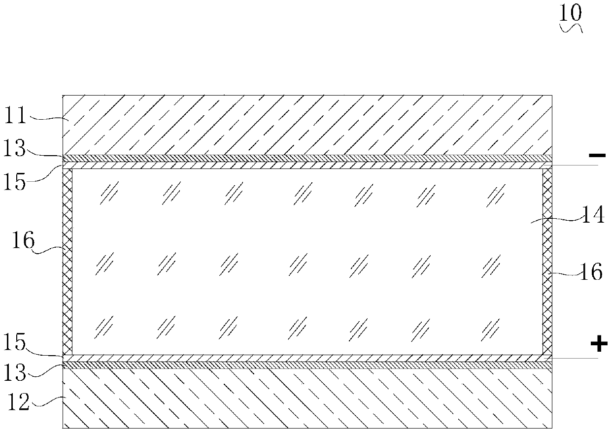
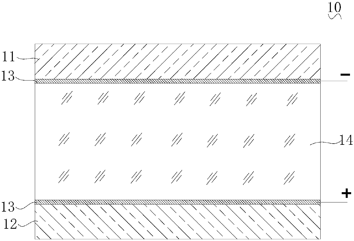
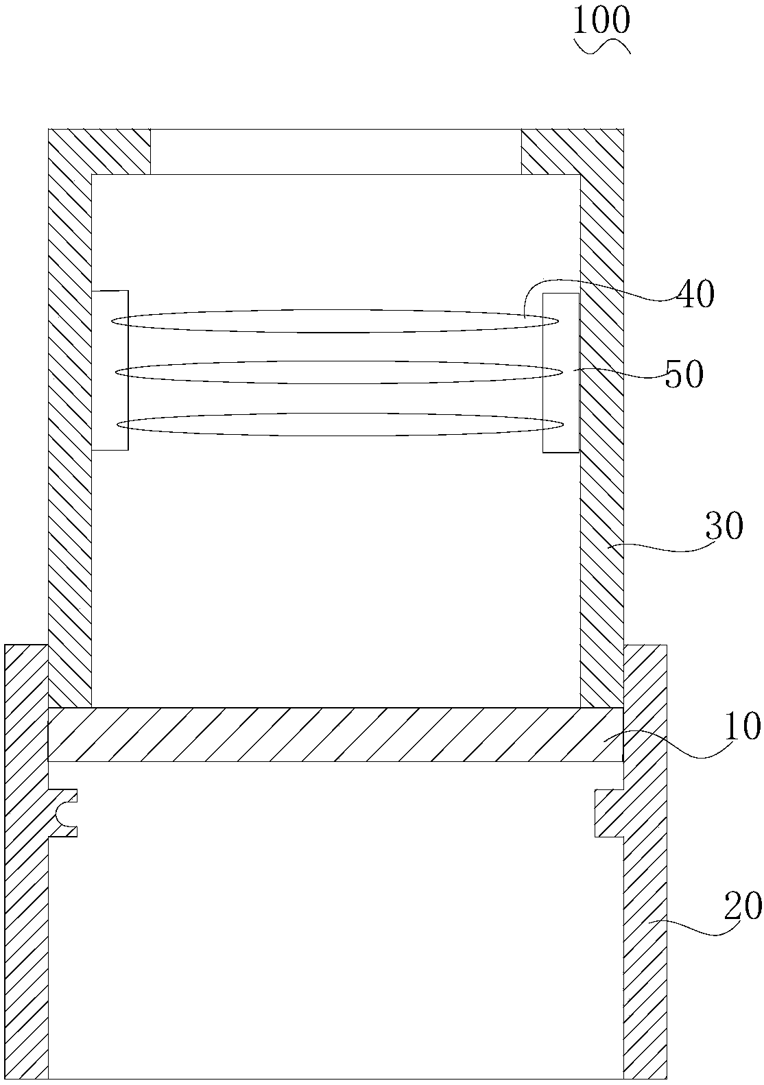
The invention discloses an optical filterer. The optical filterer comprises a first lens, a second lens and a transparent light guide medium. The first lens and the second lens are arranged oppositelyto each other in a spaced mode, and the two opposite surfaces of the first lens and the second lens are both provided with high-reflective film layers. The light guide medium is arranged between thehigh-reflective film layers, and the refractive index of the light guide medium can be changed under the effect of an external electric field to change the wavelength of light passing through the optical filter. The invention further discloses a lens module and an imaging module. In the optical filterer, the refractive index of the light guide medium can be changed to change the wavelength of thetransmitted light of the optical filter by changing the external electric field instead of relatively moving the first and second lenses, a space for meeting the movement requirements of the first lens or the second lens and an actuator for driving the lenses to move do not need to be arranged on the optical filterer, and the optical filter is small in overall thickness and simple in structure.

Description

technical field [0001] The invention relates to the field of imaging technology, and more specifically, to an optical filter, a lens module and an imaging module. Background technique [0002] Generally, the variable filter device includes two mirrors, and a high reflection film is coated on the opposite plane of the two mirrors to form a Fabry-Perot interferometer, and the distance between the two mirrors can be changed by making the two mirrors move relative to each other. , to change the wavelength of the transmitted light of the variable filter device, however, in order to meet the needs of the movement of the lens, the overall thickness of the variable filter device is relatively large. Contents of the invention [0003] The embodiments of the present invention provide an optical filter, a lens module and an imaging module. [0004] The optical filter of the embodiment of the present invention comprises: [0005] a first lens and a second lens arranged oppositely at...

Claims


Application Information

Patent Timeline
IPC IPC(8): G02F1/21G02F1/01G02B5/28G03B11/00
Inventor 曾元清
Owner GUANGDONG OPPO MOBILE TELECOMM CORP LTD
Why Eureka
Try Eureka