System for detecting the pressure in a vehicle tyre and/or speed of the vehicle

A technology for vehicles and tires, which is applied in the direction of measuring fluid pressure, linear/angular velocity measurement, and devices using electric/magnetic methods. It can solve problems such as inaccuracy and no consideration of tread pattern interference, and achieve the goal of increasing system costs. Effect

Active Publication Date: 2009-09-02
THE GOODYEAR TIRE & RUBBER CO
View PDF1 Cites 6 Cited by
  • Summary
  • Abstract
  • Description
  • Claims
  • Application Information

AI Technical Summary

Problems solved by technology

However, the speed measured by the slope of the signal edge is a function of tire pressure and is very imprecise due to tread pattern factors
[0003] However, this prior art system does not take into account the interference caused by the tread pattern

Method used


Image

  • System for detecting the pressure in a vehicle tyre and/or speed of the vehicle
  • System for detecting the pressure in a vehicle tyre and/or speed of the vehicle
  • System for detecting the pressure in a vehicle tyre and/or speed of the vehicle

Examples


Embodiment Construction

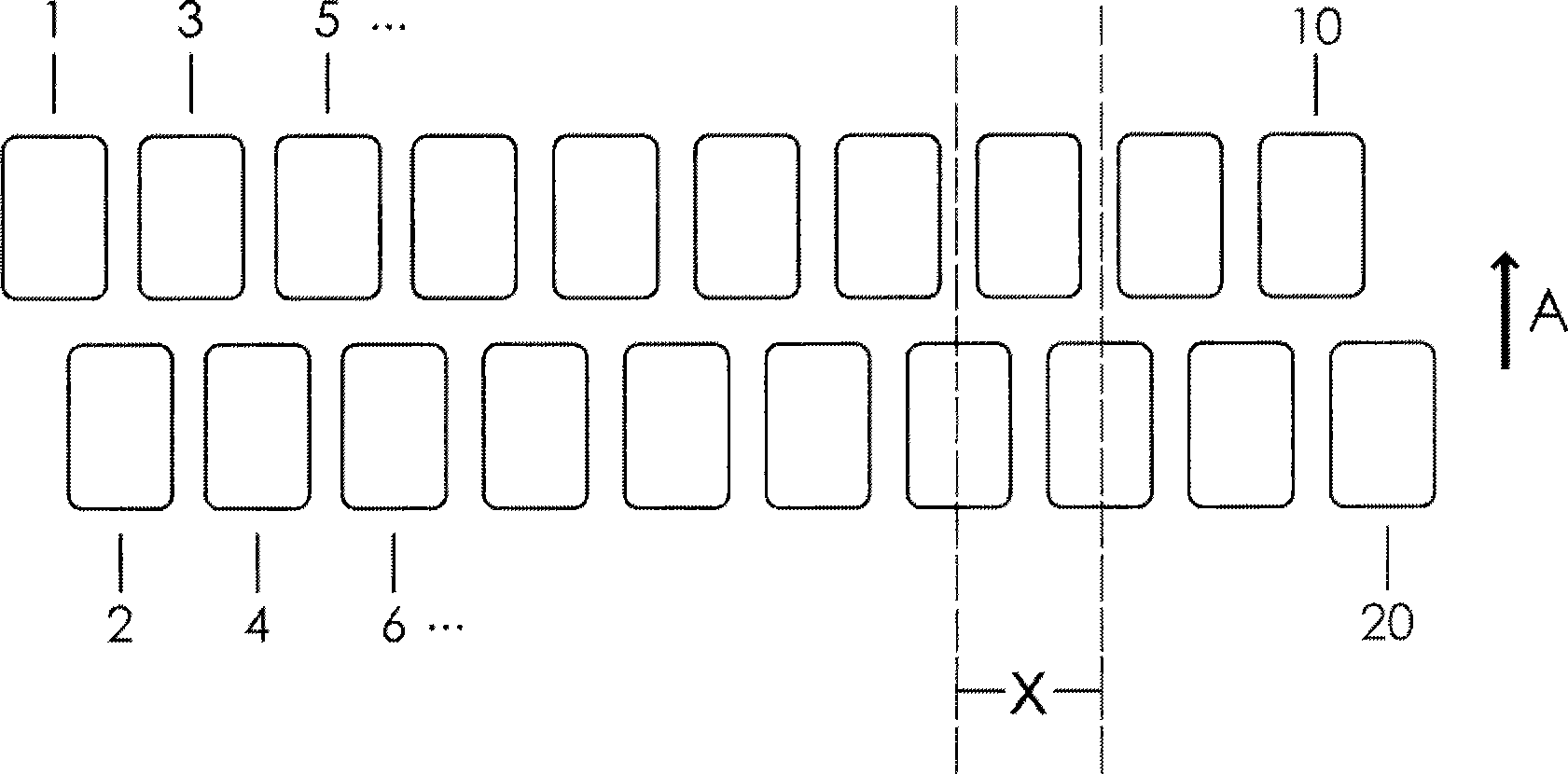
[0032] The forward direction is indicated by arrow A in the figures. A first load sensor row 10, such as the row 10 comprising 1, 3, 5, etc., is offset by an amount x transversely to the direction of travel relative to a second load sensor row 20, such as the row 20 comprising 2, 4, 6, etc. The time difference caused by the speed of the vehicle when the tire contacts the two rows 10, 20 can also be used to calculate this speed. The advantage is that the number of sensors required is only that used in the prior art line, and the invention has the advantage of also measuring velocity. The load sensors are therefore not electrically connected in series but in parallel, or they must at least be read in parallel by the computer.

[0033] The sensor surfaces must be placed at some distance from each other so that they do not overlap. A narrow gap is thus left between the sensor surfaces.

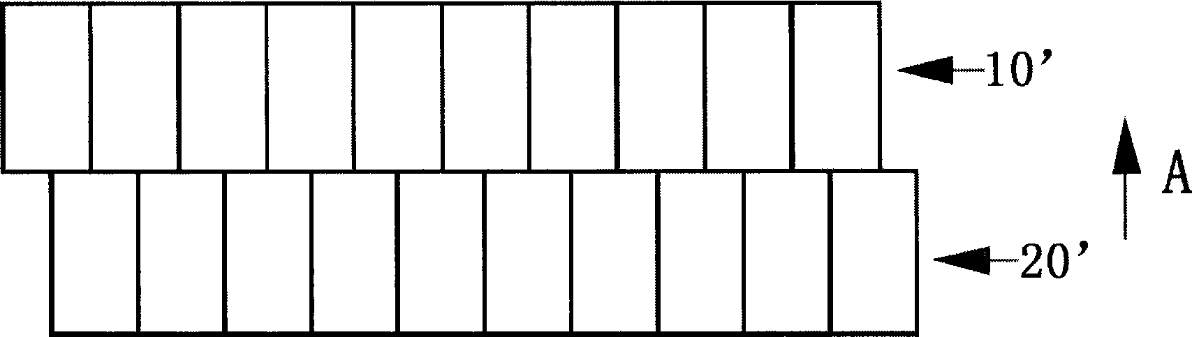
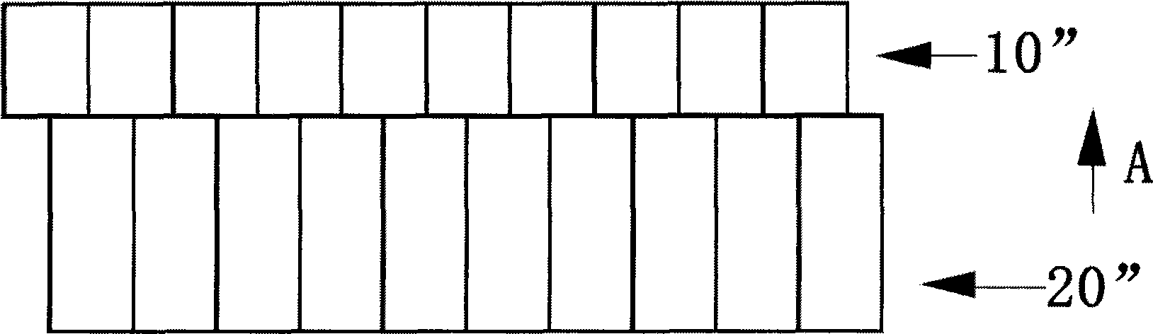
[0034] The offset arrangement allows the individual sensor surfaces to be magnified or expa...


PUM


Abstract

A system for detecting the pressure in a pneumatic vehicle tyre which is mounted on a vehicle and / or the speed of the vehicle, having an arrangement composed of load sensors which supplies force signals for a two-dimensional pattern of the distribution of force which is exerted by the vehicle tyre in contact with the sensors when the vehicle moves over the arrangement, a computer which is programmed in such a way that it defines the tyre pressure and / or the speed on the basis of the distribution of force independently of the method of manufacture or the model of the tyre and of the vehicle, and a device for displaying the pressure and / or the speed, is characterized in that the arrangement composed of load sensors comprises at least two series of load sensors which are arranged one behind the other in the direction of travel, wherein at least one row of load sensors is offset with respect to one or more rows of the load sensors by a predetermined absolute value transversely with respect to the direction of travel.

Description

technical field [0001] The present invention relates to a system for detecting the pressure and / or the speed of a vehicle in a pneumatic tire fixed to a vehicle, having a matrix of load cells supplying force signals to the vehicle as it moves over the matrix by the tire contact sensors Two-dimensional distribution pattern of applied force, having a computer programmed to determine tire pressure and / or velocity based on force distribution, independent of method of manufacture or model of tire and / or vehicle, and used to display pressure and and / or speed of the device. Background technique [0002] A system of this type for determining the pressure in a pneumatic vehicle tire is described in US5396817. In this prior art system, an arrangement of force sensors on a horizontal line on which a tire rolls is described. The speed can thus be determined via the rising and falling edges of the signal when the tire is running over the matrix of load cells. However, the velocity mea...

Claims


Application Information

Patent Timeline
Patent Type & Authority Applications(China)
IPC IPC(8): G01L17/00
CPCG01P3/66G01P3/48G01L17/005G01L17/00G01P3/00G01G19/08G01D21/02
Inventor 乌尔里希·平厄尔马丁·平厄尔
Owner THE GOODYEAR TIRE & RUBBER CO
Why Eureka
Try Eureka