
Roller for textile machinery

A technology for machinery and rollers, which is applied in the field of textile machinery rollers, which can solve problems such as endangering human health, affecting the service life of rollers, unevenness, etc., and achieve the effects of reducing hazards, improving quality, and reducing obstacles

Inactive Publication Date: 2018-12-14
SUZHOU CHENHAO TEXTILE TECH CO LTD
View PDF0 Cites 0 Cited by
  • Summary
  • Abstract
  • Description
  • Claims
  • Application Information

AI Technical Summary

Problems solved by technology

[0002] In daily life, most of the textile products are produced by large textile factories, and then become the cloth used by people after going through various processes such as printing, dyeing and printing. The formation of the cloth is usually formed by the cloth take-up roller driven by the driving device to wind the cloth on it, but the cloth often has wrinkles and unevenness after going through various processes, so the rolled up There is a quality problem with the cloth. In addition, the function of the existing mechanical roller is relatively single, which has the following disadvantages: First, due to the long-term friction and rolling between the roller and the fixed shaft, a large amount of heat is generated. If it is not handled in time, it will affect the roller. Second, in the process of mechanical operation, it is easy to produce dust, lint, thread ends, etc., which will contaminate textiles, and there will be many bacteria in textiles after heavy processing procedures, which will endanger human health

Method used

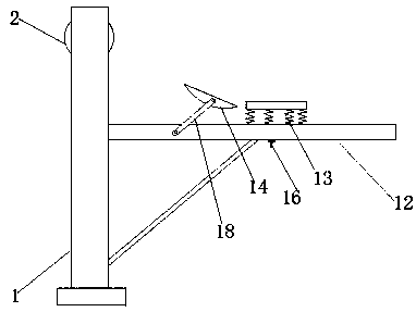
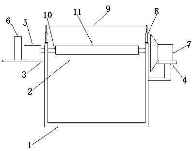

Image

  • Roller for textile machinery
  • Roller for textile machinery
  • Roller for textile machinery

Examples


Embodiment Construction

[0018] The preferred embodiments of the present invention will be described below in conjunction with the accompanying drawings. It should be understood that the preferred embodiments described here are only used to illustrate and explain the present invention, and are not intended to limit the present invention.

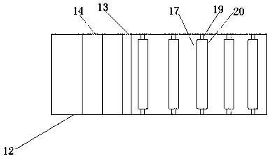
[0019] like Figure 1-4 As shown, a drum for textile machinery includes a support frame 1 and a drum body 2, and the two side walls of the support frame 1 are respectively provided with a storage board 3 and a storage table 4, and the storage board 3 is provided with a motor 5 and a A cooling fan 6, a vacuum cleaner 7 is arranged on the storage table 4, a germicidal lamp 9 is connected to the top of the support frame 1 through a pole 8, the drum body 2 includes an inner drum layer 10 and an outer drum layer 11, the A hollow interlayer is arranged between the outer drum layer 11 and the inner drum layer 10, one end of the inner drum layer 10 penetrates the side wall ...


PUM


Abstract

The invention relates to a roller for textile machinery. The roller comprises a support frame and a roller body, and a storage plate and a storage platform are correspondingly arranged on the two sidewalls of the support frame. A motor and a cooling fan are arranged on the storage plate, and a dust collector is arranged on the storage platform. The top of the support frame is connected with a germicidal lamp. The roller body comprises an inner roller layer and an outer roller layer, and a hollow interlayer is arranged between the outer roller layer and the inner roller layer. One end of the inner roller layer penetrates through the side walls of the support frame to be connected with the output end of the motor, and the other end of the inner roller layer is fixed to the side walls of thesupport frame through a rotating shaft. One side of the support frame is connected with a fabric guide platform, and a spring extrusion plate and a cambered fabric guide plate are arranged on the fabric guide platform. Fixed rods are arranged on the two sides of the spring extrusion plate, and a screw thread is arranged at the bottom of each fixed rod. The roller is various in function and simplein operation and meets a variety of needs of the roller in the using process.

Description

technical field [0001] The invention relates to a drum for textile machinery, which belongs to the field of textile machinery equipment. Background technique [0002] In daily life, most of the textile products are produced by large textile factories, and then become the cloth used by people after going through various processes such as printing, dyeing and printing. The formation of the cloth is usually formed by the cloth take-up roller driven by the driving device to wind the cloth on it, but the cloth often has wrinkles and unevenness after going through various processes, so the rolled up There is a quality problem with the cloth. In addition, the function of the existing mechanical roller is relatively single, which has the following disadvantages: First, due to the long-term friction and rolling between the roller and the fixed shaft, a large amount of heat is generated. If it is not handled in time, it will affect the roller. Second, in the process of mechanical ope...

Claims


Application Information

Patent Timeline
Patent Type & Authority Applications(China)
IPC IPC(8): B65H18/10B65H18/02B65H23/035B65H23/34
CPCB65H18/10B65H18/028B65H23/035B65H23/34B65H2701/174
Inventor 吴媛媛
Owner SUZHOU CHENHAO TEXTILE TECH CO LTD
Learn More