

Pressure type dynamic sand filter
A technology of sand filter and pressure type, which is applied in the direction of filtration separation, filtration circuit, chemical instruments and methods, etc., and can solve problems such as inability to work continuously
Inactive Publication Date: 2011-01-05
福建省江南冷却科技有限公司
View PDF0 Cites 0 Cited by
- Summary
- Abstract
- Description
- Claims
- Application Information
AI Technical Summary
Problems solved by technology
The purpose of the present invention is to overcome the defect that ordinary pressure sand filters cannot work continuously, and provide a pressure dynamic sand filter that can continuously clean the filter material and work continuously
Method used
View moreImage
Smart ImageViewing Examples

Examples
Embodiment Construction
Login to View More PUM
 Abstract
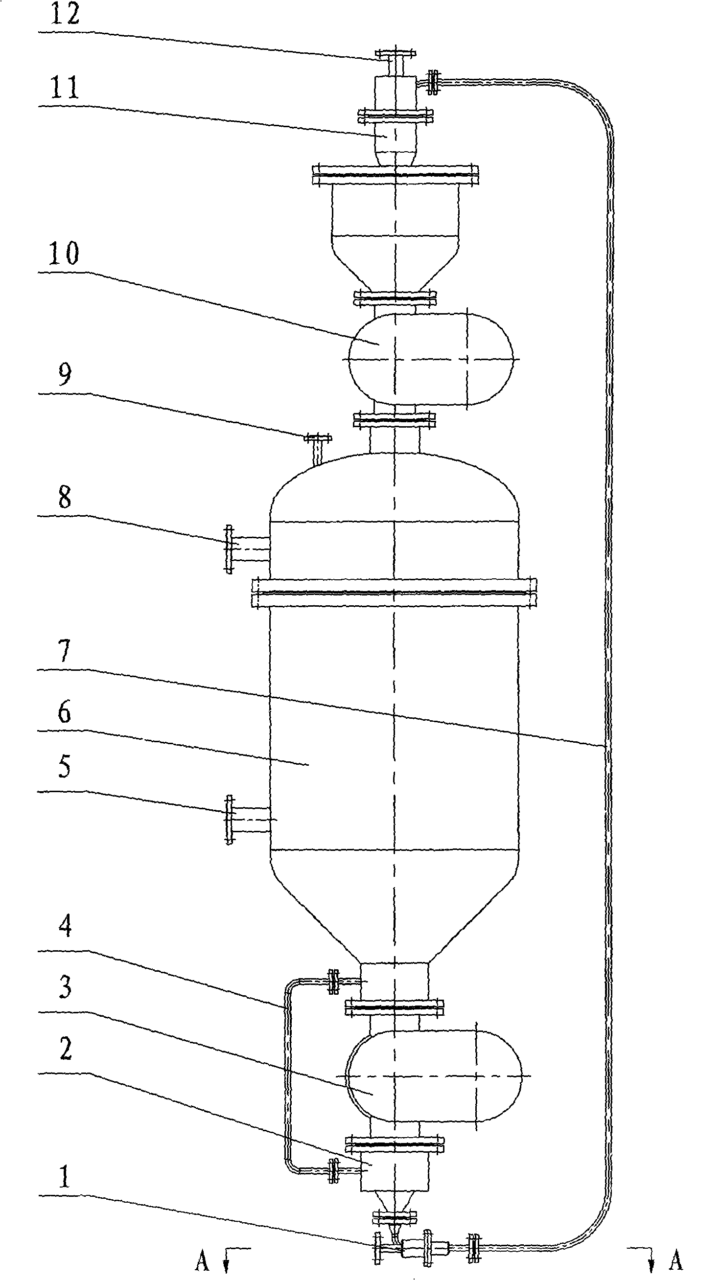
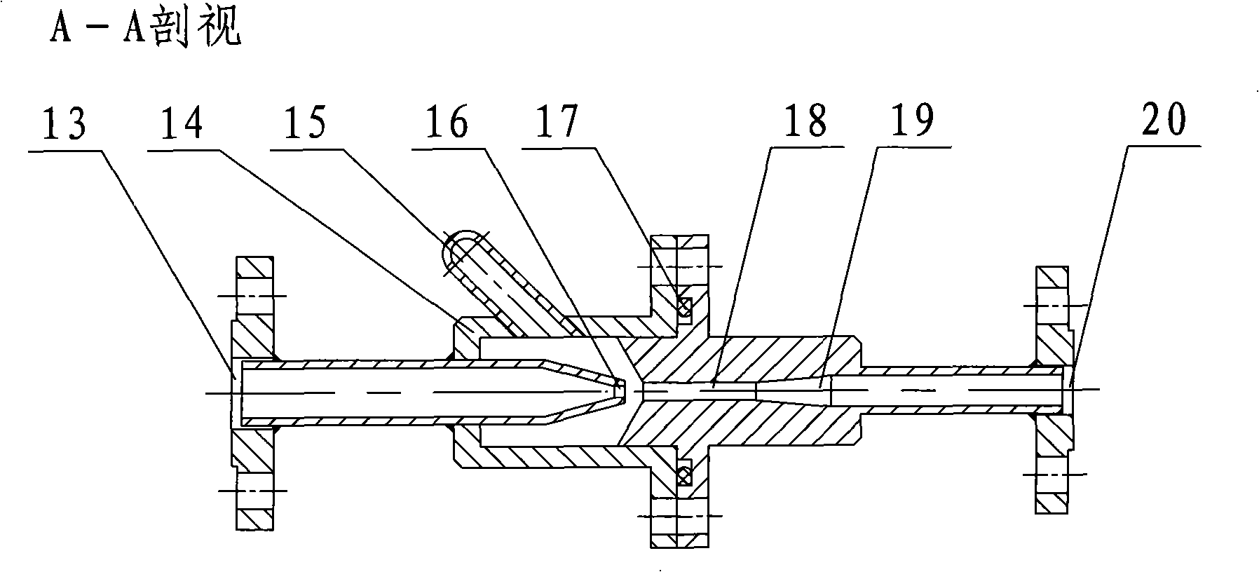
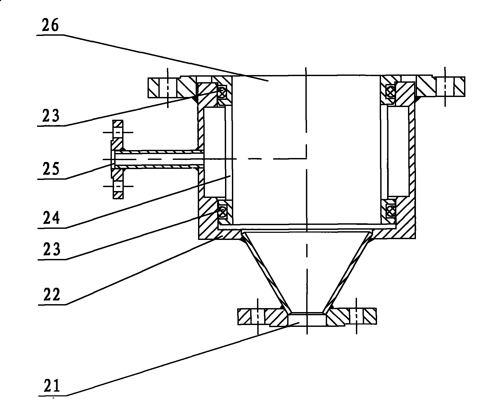
The present invention provides a pressure type dynamic sand filter. The invention relates to a sand filter applied for liquid filtering, and especially to a pressure type dynamic sand filter which cancontinuously wash the filter material. The aim of the invention is to overcome a defect that the common pressure type sand filter can not operate continuously, and provide the pressure type dynamic sand filter which can clean the filter material and operate continuously. The invention is mainly characterized in that the pressure type dynamic sand filter is composed of a sand filter tank body, a sand distribution valve, a sand-water separator, a bypass pipe, a sand conveyor, a sand conveying pipe and a sand washer. The sand filter tank body is internally installed with a water distribution ring, a flow guiding sand cone, a sand outlet filter element, a water outlet filter element, a sand dropping pipe and a sand distribution cone. When the pressure type dynamic sand filter operates normally, the raw water passes through a water inlet, the water distribution ring and the filter material layer, and is discharged from the water outlet filter element and the water outlet after filtering. Simultaneously the filter material is washed continuously through the sand distribution valve, the sand conveyor, the sand conveying pipe and the sand washer, and then drops into the sand filter tank body and forms a circulation.
Description
Pressure dynamic sand filter technical field The invention relates to a pressure type dynamic sand filter, which relates to a sand filter used in liquid filtration, in particular to a pressure type dynamic sand filter which can continuously clean the filter material. Background technique Ordinary pressure sand filters cannot work continuously. After working for a period of time, the filter material is blocked by suspended solids in the raw water, and it needs to stop working and reverse wash the filter material with clean water. Therefore, when the system needs continuous water supply, it is necessary to use two ordinary pressure sand filters to form a method of one for use and one for backup. Therefore, the complexity of equipment control, equipment investment cost and equipment footprint are increased. Contents of the invention The purpose of the present invention is to overcome the defect that common pressure type sand filters cannot work continuously, and provide a...
Claims
Login to View More Application Information
Patent Timeline
 Patent Type & AuthorityPatents(China)
IPC IPC(8): B01D36/00
Inventor蒋介民
Owner福建省江南冷却科技有限公司