Supercharge Your Innovation With Domain-Expert AI Agents!

Panel structure of plasma display device

A display device and plasma technology, applied to solid cathode components, cold cathode tubes, etc., can solve problems such as uneven image quality, abnormal discharge characteristics of plasma display units, etc.

Inactive Publication Date: 2009-11-04
AU OPTRONICS CORP
View PDF0 Cites 0 Cited by
  • Summary
  • Abstract
  • Description
  • Claims
  • Application Information

AI Technical Summary

Problems solved by technology

[0007] In view of this, in order to solve the above problems, the main purpose of the present invention is to utilize the adsorption layer adsorption to concentrate on the impure substances near the vent hole and in the air extraction-filling pipe during the air extraction process, so as to avoid improper control of the air extraction-baking steps. Or the impure substances remaining in the pores of the air extraction-gas filling pipe enter the display area through the subsequent gas filling or sealing steps to cause abnormal discharge characteristics of the plasma display unit, so as to further prevent the local area map of the plasma display device from appearing. uneven image quality

Method used


Image

  • Panel structure of plasma display device
  • Panel structure of plasma display device
  • Panel structure of plasma display device

Examples


Embodiment Construction

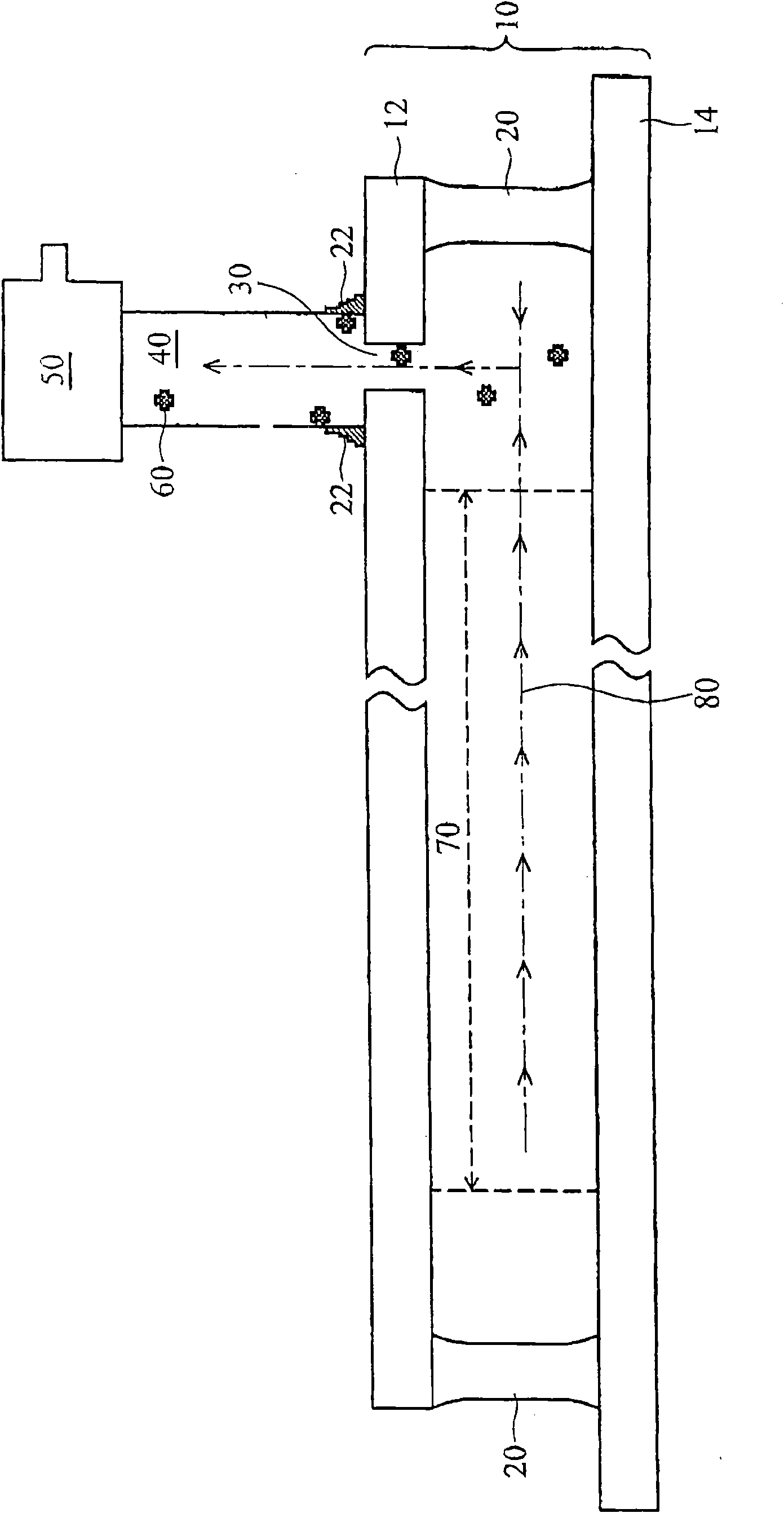
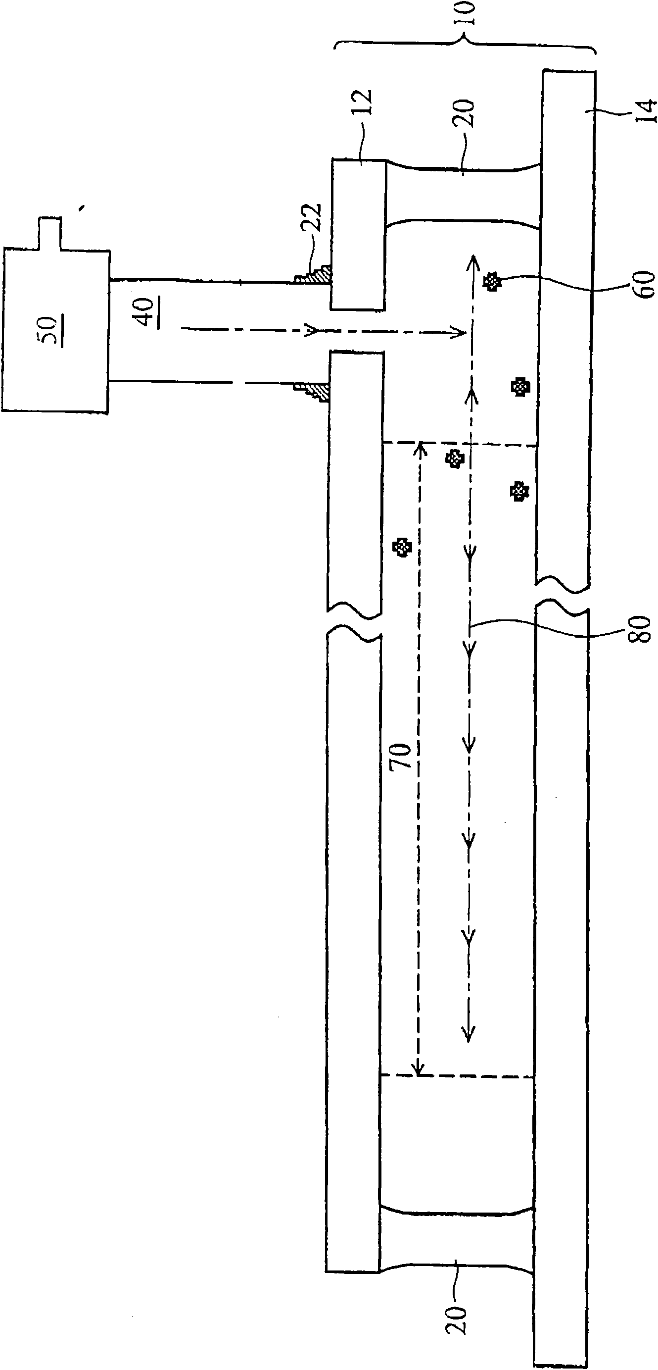
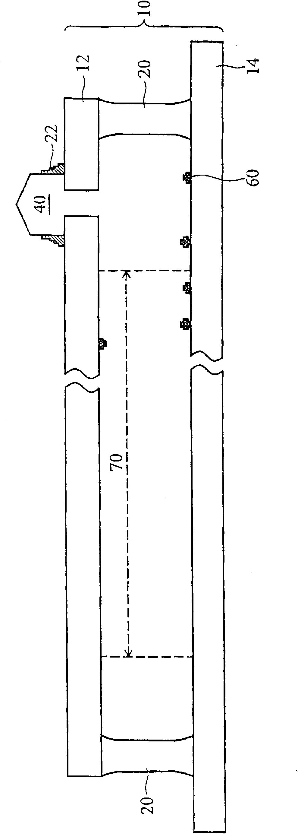
[0039]The feature of the panel structure of the plasma display device of the present invention, which improves the discharge characteristics of the plasma display unit, is that an adsorption layer is formed in the area near the vent hole of the substrate and (or) the inner side of the air extraction-filling pipe. During the gas-filling and sealing steps, the impurity generated in the process of forming the display area, pumping-filling and sealing can be effectively concentrated and adsorbed outside the display area to keep the plasma The plasma display unit in the display unit is functioning normally.

[0040] Hereinafter, the panel structure of the plasma display device capable of improving the discharge characteristics of the plasma display unit of the present invention will be described in detail with reference to the drawings and taking the rear substrate of the plasma display device as an example.

[0041] First, see figure 2 . This figure shows a preferred embodiment...


PUM


Abstract

The invention discloses a panel structure of a plasma display device. The invention mainly aims to utilize an absorption layer to absorb impure substances centralized near a vent hole and in a deflation-inflation pipe during the deflation, and avoid the discharge characteristic abnormality of a plasma display unit caused by improper control of a deflation-roasting step or the re-entrance of impure substances remained in pores of the deflation-inflation pipe into a display area through a subsequent inflation or pipe-sealing step, further to prevent the phenomenon of non-uniform image quality of a local area of the plasma display device.

Description

[0001] This application is a divisional application of the invention patent application No. 200410030055.3 with the filing date of March 18, 2004, entitled "Plasma Display Device and Its Panel Structure". technical field [0002] The invention relates to a structure of a plasma display device, in particular to a structure of a plasma display device which improves the discharge characteristics of a plasma display unit. Background technique [0003] In recent years, various new flat panel displays (FPDs), such as liquid crystal displays (LCD), organic light emitting diodes (OLEDs) and plasma displays (plasma display panels, PDP), and there is a tendency to gradually replace the traditional cathode ray tube (cathode ray tube, CRT). Among them, the plasma display is a flat-panel display that emits light by means of gas discharge, and its biggest feature is that it is light, thin, easy to enlarge and has no viewing angle problem. [0004] Please refer to Figures 1A to 1C , whic...

Claims


Application Information

Patent Timeline
Patent Type & Authority Applications(China)
IPC IPC(8): H01J17/16H01J17/49
Inventor 陈柏丞吴俊翰
Owner AU OPTRONICS CORP
Features
  • R&D
  • Intellectual Property
  • Life Sciences
  • Materials
  • Tech Scout
  • Unparalleled Data Quality
  • Higher Quality Content
  • 60% Fewer Hallucinations
Learn More