Switch arc suppression circuit for switch devices and control method thereof

A technology of arc suppression circuit and switch, which is applied in the direction of circuits, electric switches, electrical components, etc., which can solve the problems of unfavorable promotion and use, unfavorable popularization and use, large voltage drop, etc., so as to facilitate promotion and popularization, and eliminate arcing phenomenon , The effect of reducing manufacturing costs

Inactive Publication Date: 2011-07-27
沈永年 +1
View PDF0 Cites 0 Cited by
  • Summary
  • Abstract
  • Description
  • Claims
  • Application Information

AI Technical Summary

Problems solved by technology

[0002] All kinds of switches, sockets, breakers, AC contactors, relays and other switching appliances often produce arcing when they are closed or disconnected, which not only seriously damages the contacts of the switching appliances, but also causes various accident hazards to the electrical circuit; In order to eliminate the arcing phenomenon of switching appliances, there are mainly the following methods to overcome the arcing in the prior art:
[0003] (1) Vacuum arc extinguishing chamber or SF6 arc extinguishing device is used to eliminate arc, especially in the field of high voltage and high current. Although this kind of arc extinguishing device overcomes the arc phenomenon and can achieve better arc extinguishing effect, its own structure Complicated, high manufacturing cost, difficult maintenance, limited service life, not conducive to popularization and use
[0004] (2) Use solid-state relays instead of ordinary relays to eliminate arcs, especially in the field of automation control. Although this kind of arc extinguishing device also overcomes the arc phenomenon and can achieve better arc extinguishing effects, it also has a complex structure. The defects of high manufacturing cost and difficult maintenance, and the defects of easy heating of the circuit, limited service life and carrying capacity, are also not conducive to popularization and use
[0005] (3) At present, there is another method of eliminating arc with better effect, which is the main and auxiliary switch arc suppression circuit. The method is to connect an auxiliary circuit (such as a large breaker, etc.) When the circuit and the main switch are closed or disconnected, a simple logical relationship is formed first and then to achieve the arc suppression effect. Although this arc suppression method can effectively overcome the arc phenomenon to a certain extent, it has the following defects: First, its The internal resistance of the auxiliary circuit is relatively large, and the voltage drop is large when it is turned on; secondly, when the working circuit of the switching device is an AC circuit and the load is an inductive load, there is a surge current, and the auxiliary circuit cannot effectively overcome these problems. The impact of surge current, these will cause a certain degree of arcing phenomenon when the main switch is turned on and off, and even damage the switching device in severe cases

Method used


Image

  • Switch arc suppression circuit for switch devices and control method thereof
  • Switch arc suppression circuit for switch devices and control method thereof
  • Switch arc suppression circuit for switch devices and control method thereof

Examples


Embodiment 1

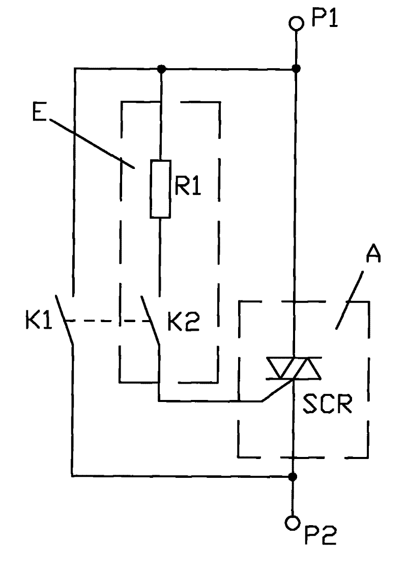
[0038] Example 1, such as figure 2 Shown:

[0039] The switch arc suppression circuit specifically includes a main switch K1, a control circuit C and a controllable three-terminal circuit A; wherein the main switch K1 is a mechanical switch, and the control unit E in the control circuit C is a group connected in series A combined circuit composed of a current-limiting resistor R1 and a mechanical trigger signal switch K2 in the circuit; the controllable three-terminal circuit A is a bidirectional thyristor SCR switch circuit.

[0040] working principle:

[0041] Connecting the switching device into the working circuit;

[0042] Switching electrical closing process:

[0043] Such as figure 2 As shown, the switching device is in the initial state when it is disconnected; according to the control method of the arc suppression circuit, the mechanical trigger signal switch K2 is first contacted and closed in an approximately arc-free state, and the controllable three-terminal...

Embodiment 2

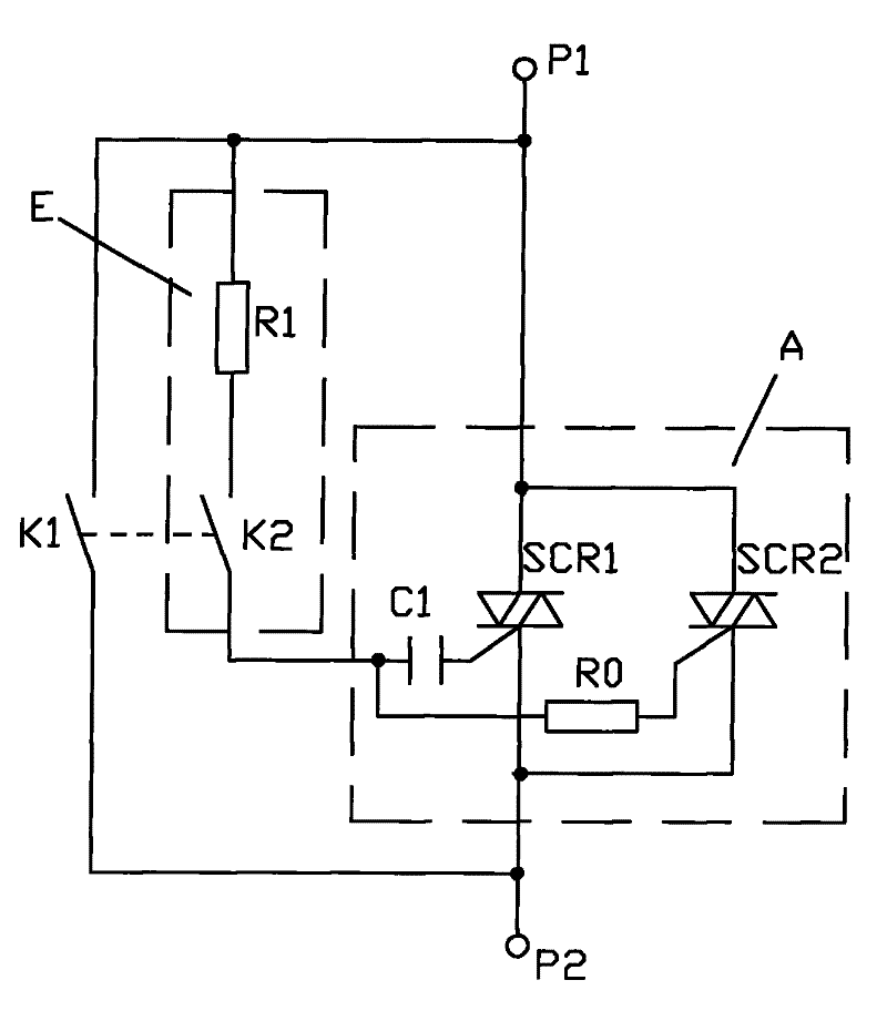
[0046] Example 2, such as image 3 Shown:

[0047] The switch arc suppression circuit specifically includes a main switch K1, a control circuit C and a controllable three-terminal circuit A; wherein the control unit E in the control circuit C is a group of current-limiting resistors R1 and mechanical triggers connected in series in the circuit A combined circuit composed of a signal switch K2; the controllable three-terminal circuit A is a combined circuit composed of two bidirectional thyristors connected in parallel and a capacitor C1 and a resistor R0 connected in series therein.

[0048] working principle:

[0049] Connecting the switching device into the working circuit;

[0050] Switching electrical closing process:

[0051] Such as image 3 As shown, the switching device is in the initial state when it is disconnected; according to the arc suppression circuit control method, the mechanical trigger signal switch K2 is first contacted and closed in an approximately ar...

Embodiment 3

[0054] Example 3, such as Figure 4 Shown:

[0055] The switch arc suppression circuit specifically includes a main switch K1, a control circuit C and a controllable three-terminal circuit A; wherein the main switch K1 is a mechanical switch, and the control unit E in the control circuit C is a group connected in series A combination circuit composed of a current limiting resistor R1 and a mechanical trigger signal switch K2 in the circuit; the controllable three-terminal circuit A is a combination circuit composed of two parallel bidirectional thyristors SCR1 and SCR2.

[0056] working principle:

[0057] Connecting the switching device into the working circuit;

[0058] Switching electrical closing process:

[0059] Such as Figure 4 As shown, the switching device is in the initial state when it is disconnected; according to the control method of the arc suppression circuit, the mechanical trigger signal switch K2 is first contacted and closed in an approximately arc-fre...


PUM


Abstract

The invention relates to a switch arc suppression circuit and a control method thereof. The switch arc suppression circuit comprises a main switch K1, a controllable three-terminal circuit A and a control circuit C; the main point is that a control unit E of the control circuit C is a combination circuit composed of a base bias resistor R3, an electron trigger signal switch T2, an electron trigger signal input port Vi, a triode T1, a regulated power supply voltage terminal Vcc, a regulated power supply earthing terminal GND, a collector bias resistor R2, an optical coupler IC and a limit current resistor R1. The invention excellently solve the serious technical problems of igniting, arcing phenomena that are difficult to solve by the similar products structure; the control method is improved; and the invention is featured with large current-carrying capacity, low cost, long service life, small size, convenient installation and use, and wide using range without arcing, and is suitable for popularizing in electrical appliance field.

Description

technical field [0001] The invention relates to the field of electrical appliances, and relates to an arc suppression circuit and a control method thereof for preventing switching electrical appliances from pulling arcs when they are closed or disconnected. Background technique [0002] All kinds of switches, sockets, breakers, AC contactors, relays and other switching appliances often produce arcing when they are closed or disconnected, which not only seriously damages the contacts of the switching appliances, but also causes various accident hazards to the electrical circuit; In order to eliminate the arcing phenomenon of switching appliances, there are mainly the following methods to overcome the arcing in the prior art: [0003] (1) Vacuum arc extinguishing chamber or SF6 arc extinguishing device is used to eliminate arc, especially in the field of high voltage and high current. Although this kind of arc extinguishing device overcomes the arc phenomenon and can achieve b...

Claims


Application Information

Patent Timeline
Patent Type & Authority Patents(China)
IPC IPC(8): H01H9/30H01H9/54
Inventor 沈永年顾诚
Owner 沈永年
Why Eureka
Try Eureka