Conveying device for leather shoe setting machine

A technology of conveying device and setting machine, which is applied in the direction of shoemaking machinery, footwear, clothing, etc., and can solve problems such as large body size, unstable shoe rack operation, and complex structure.

Inactive Publication Date: 2009-12-09
赵宽学
View PDF0 Cites 8 Cited by
  • Summary
  • Abstract
  • Description
  • Claims
  • Application Information

AI Technical Summary

Problems solved by technology

[0003] In order to solve the problem in the prior art that the shoe rack is not running smoothly and the body is large

Method used


Image

  • Conveying device for leather shoe setting machine
  • Conveying device for leather shoe setting machine

Examples


Embodiment Construction

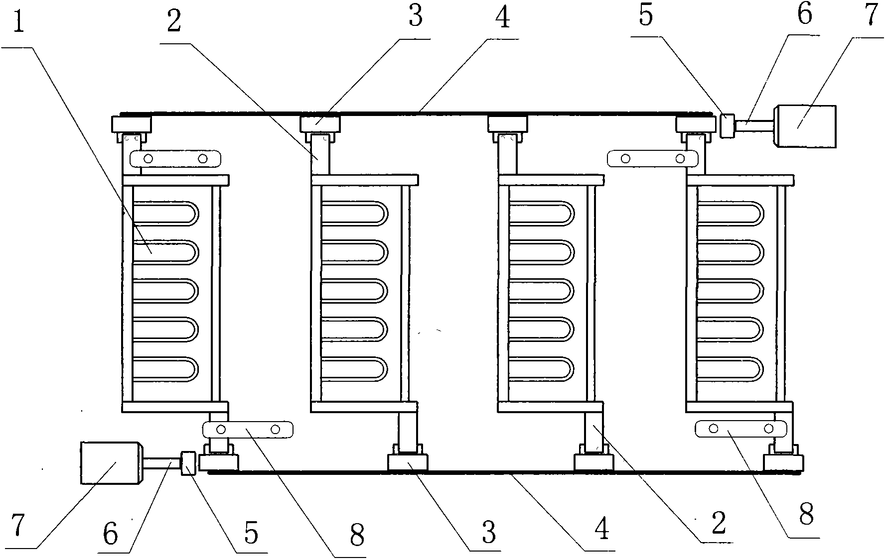
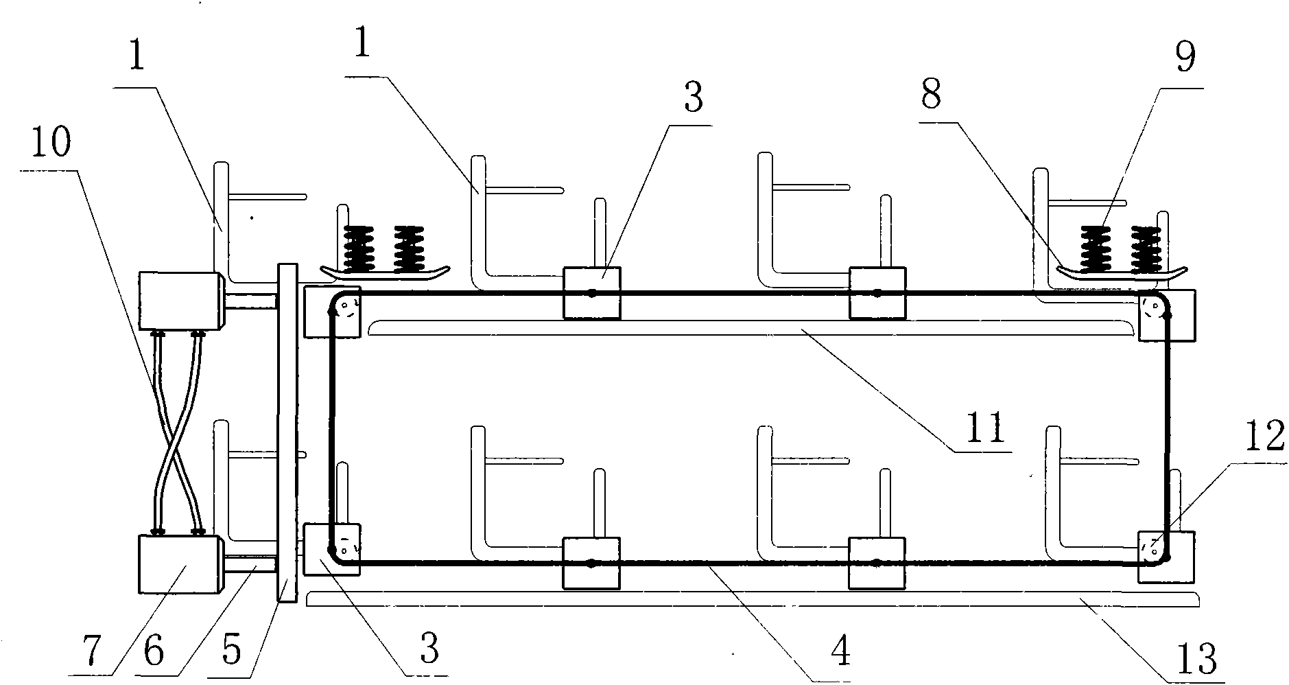
[0023] Such as figure 1 , figure 2 As shown, a conveying device for a leather shoe shaping machine includes a shoe rack 1, a chain 4, an upper guide rail 11, a lower guide rail 13, a slider 3, a slide bar 5 and a baffle plate 8. A supporting plate 2 is respectively installed at both ends of the bottom of the shoe rack 1, and the two supporting plates 2 are installed in a staggered manner. 2 are not installed on the same axis, when the supporting plate 2 is movably installed on the chain 4, the shoe rack 1 will not overturn. The shoe rack 1 is driven by the synchronous rotation of the chains 4 on both sides. The chain 4 is annular and closed, and is formed into a square under the support of four guide pulleys 12. The two chains 4 have the same length and are installed in parallel, but they are staggered forward and backward. It just happens to be the staggered distance between the supporting plates 2 at both ends of the bottom of the shoe rack 1, so that when the two chains ...


PUM


Abstract

The invention discloses a conveying device for a leather shoe setting machine, which comprises a shoe rack, chains, an upper guide rail, a lower guide rail, a slide block, a slide bar and a baffle plate. Two ends of the bottom of the shoe rack are provided with a supporting plate respectively, the two supporting plates are arranged in a staggered mode, one supporting plate at the left end is arranged close to the rear side of the shoe rack, and the other supporting plate at the right end is arranged close to the front side of the shoe rack. The shoe rack is driven by synchronous rotation of the chains at two sides, the two chains have the same length and are arranged in parallel and staggered in a certain interval from the front to back, and the interval is just the staggered interval of the supporting plates at the two ends of the bottom of the shoe rack. Because the two conveying chains of the conveying device for the leather shoe setting machine are arranged in a staggered mode from the front to back, and the horizontal motion direction and the vertical motion direction of the conveying chains are provided with the baffle plate, the slide block and the slide bar, the shoe rack is stable when cyclically moving in the horizontal and vertical directions.

Description

technical field [0001] The invention relates to a shoe-making machine, in particular to a shoe-setting machine. Background technique [0002] The leather shoes setting machine is mainly composed of a setting processing box, a conveying device, a shoe rack and a control circuit system. The shoe rack is used to place and fix the shoes, and the shaping treatment box is used to shape, soften, and wrinkle the leather shoes. Loop delivery. There is a circular shaft at the bottom of the shoe rack of the existing leather shoe shaping machine, and the shoe rack is installed on the left and right conveying chains by these two circular shafts. The two conveying chains rotate synchronously under the action of the control circuit to drive the shoe rack into the The sizing processing box is used for sizing treatment, and after the shoes on the shoe rack are processed, the conveyor chain transports the shoe rack to the outside of the sizing processing box. The shoe rack is installed on ...

Claims


Application Information

Patent Timeline
IPC IPC(8): A43D117/00A43D111/00
Inventor 赵宽学
Owner 赵宽学
Why Eureka
Try Eureka