Mobile terminal device

A mobile terminal and shell technology, applied in the direction of support structure installation, telephone structure, branch office equipment, etc., can solve problems such as difficult to form gaps, and achieve the effect of fast pressing

Inactive Publication Date: 2009-12-09
PANASONIC CORP
View PDF3 Cites 5 Cited by
  • Summary
  • Abstract
  • Description
  • Claims
  • Application Information

AI Technical Summary

Problems solved by technology

However, in the thin slide type mobile phone device 80, it is difficult to form a sufficient gap
For the case where the gap is narrow, there is a problem that the lower surface of the second housing 87 comes into contact with the protrusions 82, 84

Method used


Image

  • Mobile terminal device
  • Mobile terminal device
  • Mobile terminal device

Examples


Embodiment 1

[0058] As the mobile phone device of Embodiment 1 of the present invention, a folding type mobile phone device (or a so-called vertically and horizontally opening type mobile phone device) having biaxial hinges in which the longitudinally opened and laterally opened sides of the casing on which the display portion is located will be described. Opening can be effected, ie the housing can be opened in both longitudinal and transverse directions.

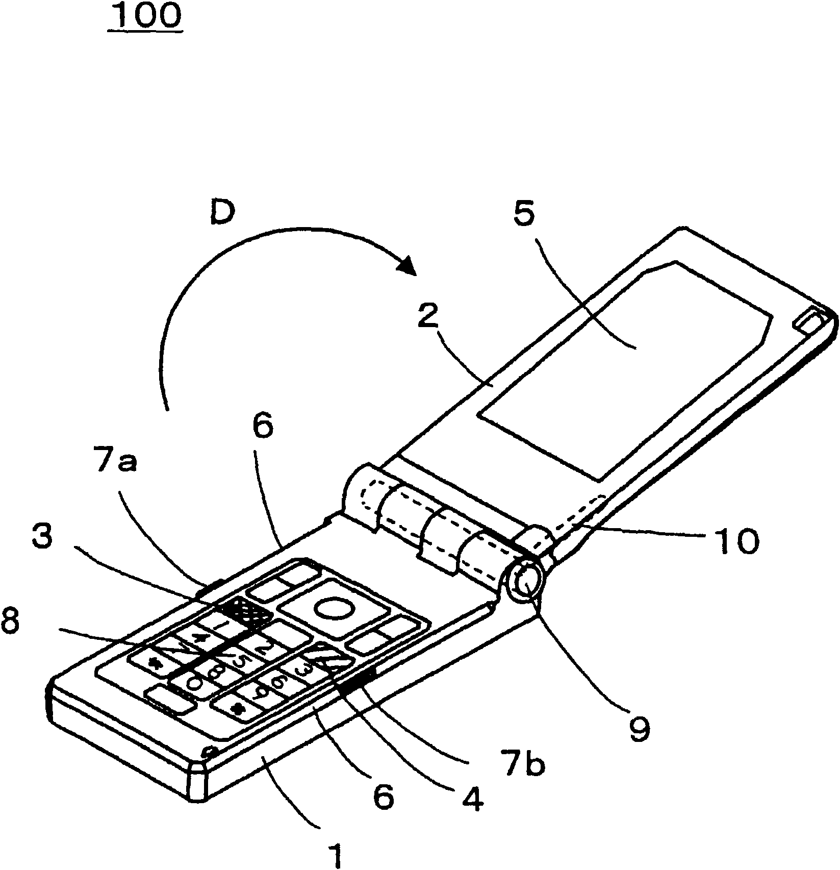
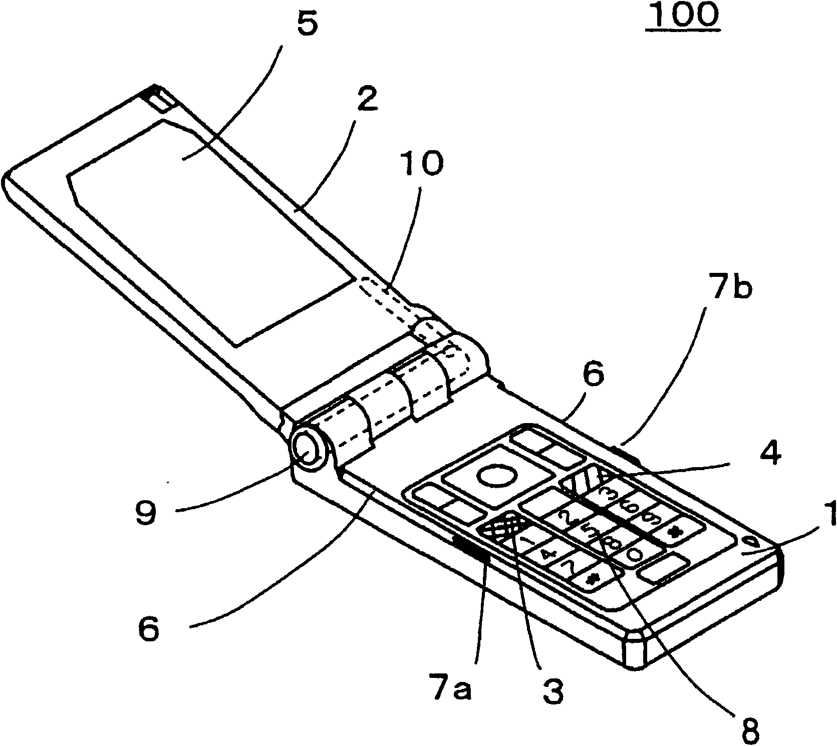
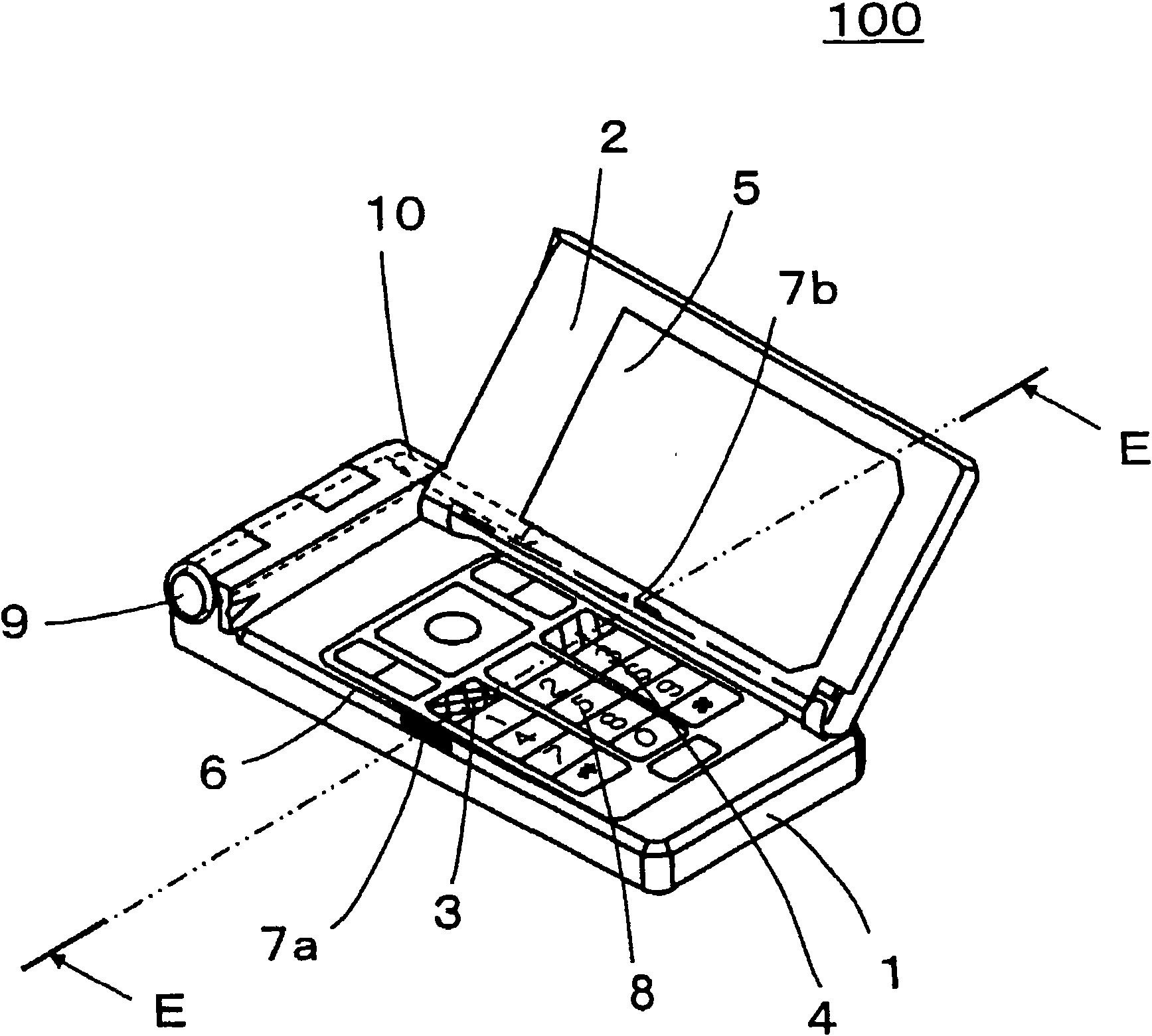
[0059] figure 1 and 2 It is a perspective view showing the appearance of the mobile phone device 100 according to Embodiment 1 of the present invention when the second housing 2 is opened from top to bottom or along the longitudinal direction. figure 1 is a perspective view of the mobile phone device 100 viewed obliquely from the upper right position, figure 2 It is a perspective view of the mobile phone device 100 viewed obliquely from the upper left position. image 3 A perspective view showing the appearance of the mobile phon...

Embodiment 2

[0080] Next, for Embodiment 2 of the present invention, a case where the present invention is applied to a slide-type mobile phone device will be described.

[0081] Figure 13 It is a perspective view showing the appearance of a slide-type mobile phone device 200 according to Embodiment 2 of the present invention. In the slide type mobile phone device 200, the second housing 22 on which the display section 25 is located slides over the first housing 21 on which the control section is located. An edge portion of the upper surface of the first housing 21 on which the control portion is located is chamfered in the vicinity of the call button 3 and the call clear button 4 provided on the upper surface, thereby forming an elongated slope 26 . In addition, a linear protrusion 27 b is provided on the slope 26 located near the call clear button 4 .

[0082] Specifically, the protrusion 27b is provided on the edge portion constituting the edge portion of the upper surface of the fir...

Embodiment 3

[0086] In Embodiment 3 of the present invention, a case where the present invention is applied to a so-called bar mobile phone device will be described. Figure 14 It is a perspective view showing the appearance of a mobile phone device 300 according to Embodiment 3 of the present invention. In the mobile phone device 300, a call button 3, a call clear button 4, a display portion 35, and the like are provided on an upper surface of a casing 31 formed in a substantially straight rectangular parallelepiped shape.

[0087] In the mobile phone device 300 , edge portions of the upper surface of the housing 31 near the call button 3 and the call clear button 4 are chamfered to form a slope 36 . In addition, a linear protrusion 37 b is provided on the slope 36 located near the call clear button 4 .

[0088] Specifically, the protrusion 37b is provided on the edge portion constituting the edge portion of the upper surface of the housing 31 at a height lower than that of the upper sur...


PUM


Abstract

The invention discloses a mobile terminal device. In a foldable mobile terminal device, a first housing is connected to a second housing via a connecting portion. The mobile terminal device includes: a first hinge shaft for opening / closing the second housing together with the connecting portion in a longitudinal direction; a second hinge shaft for opening / closing the second housing in a lateral direction; a call clearing button disposed on a second hinge shaft side of an upper surface of the first housing as seen from a lateral center of the upper surface; and a first projection for button identification which is provided on an edge portion of the second hinge shaft side and lies lateral to the call clearing button wherein a height of the first projection is made lower than a height of the upper surface of the first housing.

Description

technical field [0001] The present invention relates to a mobile terminal device, and more particularly, to a mobile phone device, PDA (Personal Digital Assistant), PHS (Personal Handyphone System), etc. in which the position of a call clear button or a call button is easily recognizable. Background technique [0002] In a conventional fixed telephone set, a protrusion is provided on the surface of the No. 5 key of the dial key, so that the position can be easily recognized by a fingertip that is allowed to touch the protrusion. Furthermore, among mobile phone devices that have been rapidly popularized recently, mobile phone devices having similar protrusions on the surface of the 5 key and other operation buttons have been put into practical use. When protrusions are provided on the surface of dial buttons and other operation buttons, it is easy to locate these buttons and thus facilitate their operation. [0003] A mobile phone device includes a so-called "call key" or "c...

Claims


Application Information

Patent Timeline
Patent Type & Authority Applications(China)
IPC IPC(8): H04M1/02H05K7/16
CPCH04M1/23H04M1/0214H04M1/0235H04M1/0222
Inventor 藤本诚司柳桥秀广
Owner PANASONIC CORP
Why Eureka
Try Eureka