Vacuum boosting device

A negative pressure, transformer chamber technology, applied in the direction of brake transmission, transportation and packaging, brakes, etc., can solve the problems of the axial length of the holding member and the complex structure of the cylindrical part, and achieve the effect of small and compact formation

Inactive Publication Date: 2010-02-17
BOSCH CORP
View PDF2 Cites 0 Cited by
  • Summary
  • Abstract
  • Description
  • Claims
  • Application Information

AI Technical Summary

Problems solved by technology

[0007] However, in this negative pressure multiplier, since the engaging position of the cylindrical member side hook and the retainer side hook is located in front of the pushed portion as described above, and the center axis of the cylindrical member passes through Partially and elastically deflects in the plane, so the holding member becomes longer in the axial direction, and accordingly becomes a large structure
In addition, since the cylindrical member not only has the vacuum valve seat, but also has the pressed portion and the cylindrical member side hook, and the portion of the cylindrical member provided with these pressed portions and the cylindrical member side hook is elastically deformed structure, so the cylindrical part becomes a complicated structure
In this way, the BA mechanism of the negative pressure multiplier device disclosed in Japanese Patent Application Laid-Open No. 2004-17740 becomes a large and complicated structure.

Method used


Image

  • Vacuum boosting device
  • Vacuum boosting device
  • Vacuum boosting device

Examples


Embodiment Construction

[0018] The best mode for carrying out the present invention will be described below using the drawings.

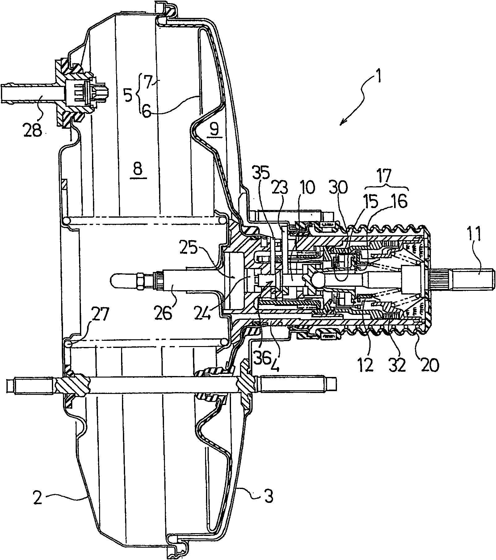
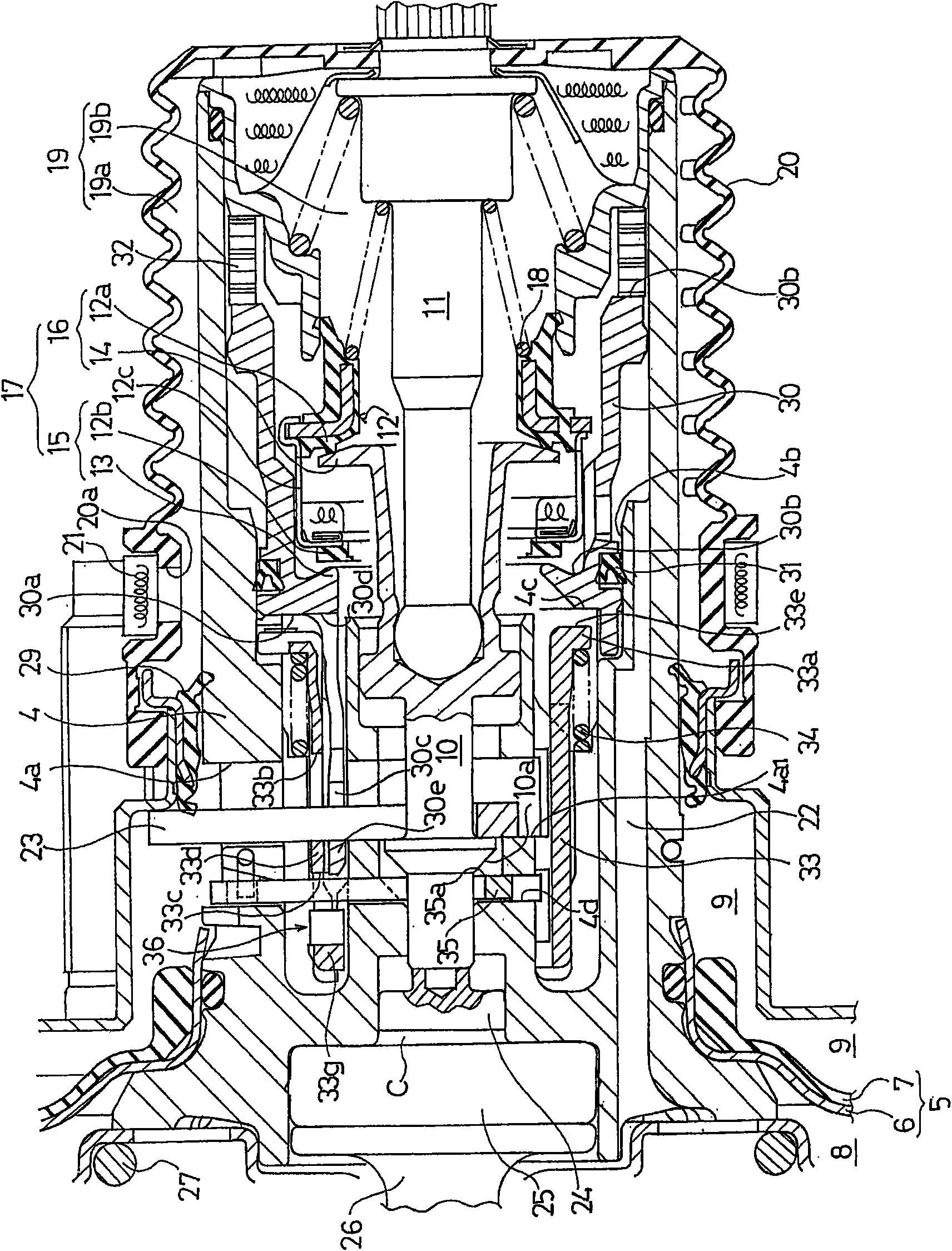
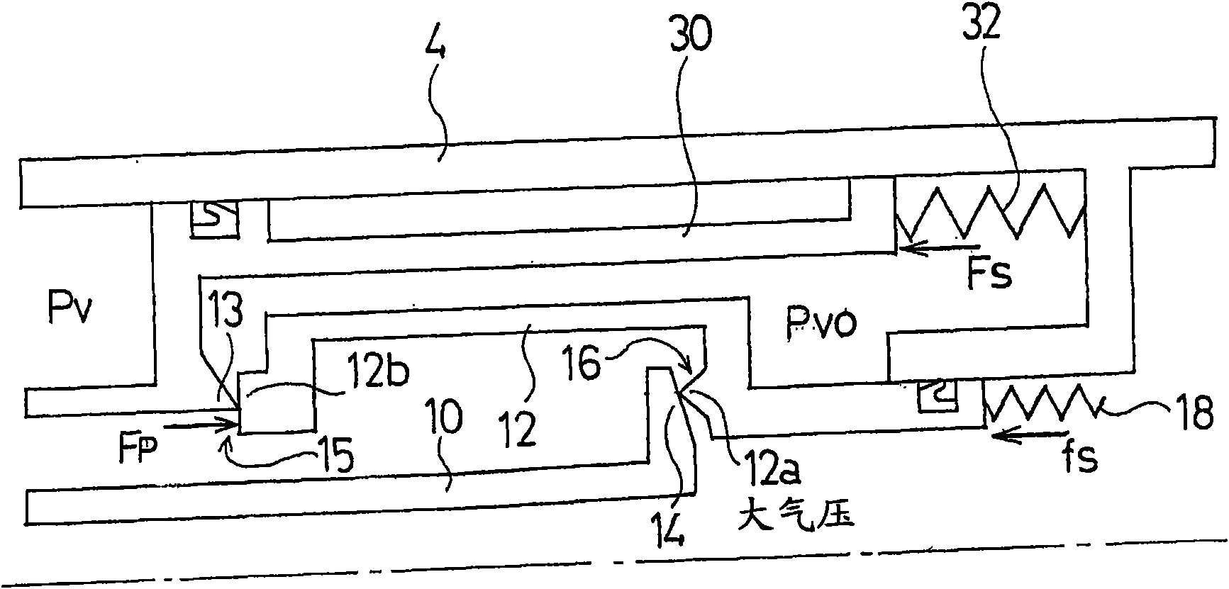
figure 1 It is a cross-sectional view showing an embodiment of the negative pressure multiplier of the present invention in a non-working state, and an example of a brake multiplier suitable for use in a braking system; figure 2 for enlarged display figure 1 Partially enlarged cross-sectional view of parts of medium vacuum valve and atmospheric valve. In addition, in the following description, "front" and "rear" represent "left" and "right" in each drawing, respectively.

[0019] First of all, with regard to the same constituent parts as the conventional negative pressure multiplier described in Patent Document 1 in this example negative pressure multiplier, and although it is different from the structure of the negative pressure multiplier described in Patent Document 1, it has nothing to do with the present invention. The components of the direct relationship will be ...


PUM


Abstract

Provided is a vacuum boosting device (1), in which a BA cylindrical member (33) is held at an inactive position, when at a BA inaction time, by a cylindrical member holding member (35). At an emergency braking time, a retention releasing portion (10a) of a valve plunger (10) pushes the cylindrical member holding member (35) so that the cylindrical member holding member (35) is elastically deformedin a plane normal to the axial direction of the BA cylindrical member (33). Then, the retention of the BA cylindrical member (33) by the cylindrical member holding member (35) is released, and the BAcylindrical member (33) is moved to a predetermined extent by a BA action spring (34), so that a vacuum valve seat member (30) and a valve member (12) move backward to predetermined extents. As a result, an atmospheric valve has a larger opening than that of the ordinary time thereby to have a higher output.

Description

Background technique [0001] The present invention relates to the technical field of a negative pressure multiplier used in a brake multiplier, and in particular, relates to the ability to obtain a higher braking force than usual with the same input (brake operating force) during emergency braking operation as in normal operation. The technical field of the negative pressure multiplier device with large output during work. In addition, in the claims and description of this patent, the direction in which the input shaft advances due to the input (i.e., the working direction) is referred to as "front", and the direction in which the input shaft returns due to the disappearance of the input is referred to as "rear". [0002] Conventionally, in the braking system of automobiles such as passenger cars, a negative pressure multiplier using negative pressure is used in the brake multiplier. In such a conventional general negative pressure multiplier, if the input shaft advances when ...

Claims


Application Information

Patent Timeline
Patent Type & Authority Applications(China)
IPC IPC(8): B60T13/57
CPCB60T13/57
Inventor 渡部悟
Owner BOSCH CORP
Why Eureka
Try Eureka