Electrical connector system having a continuous ground at the mating interface thereof

An electrical connector system and electrical connector technology, which are applied in the direction of connecting parts protective grounding/shielding device, connection, fixed connection, etc., can solve problems such as expensive connectors

Inactive Publication Date: 2013-06-12
FRAMATOME CONNECTORS INT SA
View PDF0 Cites 3 Cited by
  • Summary
  • Abstract
  • Description
  • Claims
  • Application Information

AI Technical Summary

Problems solved by technology

Although this connector is suggested to have low frequency domain crosstalk (even in the range of about 10-20 Gigabites / sec data transfer rate), the use of carbon impregnated plastic makes this connector relatively expensive

Method used


Image

  • Electrical connector system having a continuous ground at the mating interface thereof
  • Electrical connector system having a continuous ground at the mating interface thereof
  • Electrical connector system having a continuous ground at the mating interface thereof

Examples


Embodiment Construction

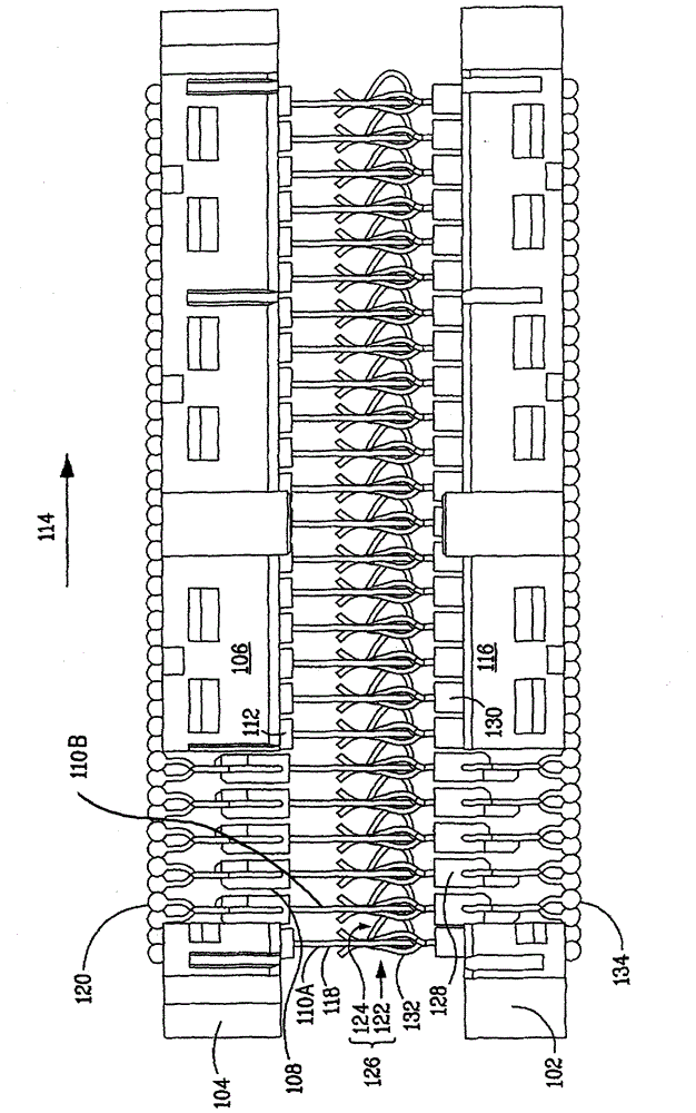
[0016] figure 1 The first electrical contact 102 is shown mated to the second electrical contact 104 with the top of each connector housing missing to show the mating interface. Mating electrical connectors 102, 104 may provide a connection interface between one or more substrates, such as printed circuit boards. For example, the first connector 102 may be mounted on a first substrate (eg, a printed circuit board), and the second connector 104 may be mounted on a second substrate (eg, a printed circuit board). The connectors 102, 104 may be high-speed electrical connectors, ie, connectors that operate at data transfer rates in excess of 1 Gbit / s (typically 10-20 Gbits / s or greater). There is a well known relationship between data transfer rate (also referred to as "bit rate") and signal rise time. That is, rise time ≈0.35 / bandwidth, where bandwidth is approximately equal to half the data transfer rate.

[0017] The first connector 102 and the second connector 104 are shown ...


PUM


Abstract

A connector interface may include an arrangement of contacts in a first connector, and a corresponding, complementary arrangement of contacts in a second connector mating with the contacts of the first connector. The contacts may be signal contacts or ground contacts. When the connectors are mated, a ground may be established between the connectors by the mating of the ground contacts from the respective connectors. The ground contacts in the first connector may be shaped to bridge together an array of ground contacts in the second connector when the connectors are mated. Such bridging tends to establish a continuous ground along the array of ground contacts, creating a more robust ground than in an otherwise identical connector.

Description

Background technique [0001] Electrical connectors provide signal connections between electronic devices using signal contacts. Often, there is undesirable interference or crosstalk between adjacent signal contacts. A common approach to reducing crosstalk includes interspersing ground contacts between signal contacts. However, at certain frequencies, the signal tends to "jump" through or across the ground contact, causing mistransmission and signal errors that are detrimental to the operation of circuits and connectors. [0002] Frequency domain techniques can help measure and estimate the signal loss and crosstalk characteristics of a connector system over a certain frequency range. Observing crosstalk in the frequency domain shows a measure of crosstalk energy at various frequencies of interest, such as data rate and important harmonics. It can be appreciated that spikes in frequency domain crosstalk are undesirable because spikes may indicate spurious voltages between gro...

Claims


Application Information

Patent Timeline
Patent Type & Authority Patents(China)
IPC IPC(8): H01R13/648
CPCH01R13/6597H01R12/52H01R13/7033H01R13/112H01R13/6471
Inventor S·斯托纳
Owner FRAMATOME CONNECTORS INT SA
Why Eureka
Try Eureka