Method for controlling operating frequency of integrated circuit

a technology of operating frequency and integrated circuit, which is applied in the direction of electric pulse generator circuit, generating/distributing signals, instruments, etc., can solve the problems of power supply voltage variation that cannot be suppressed, etc., to reduce the amount of power supply voltage undershoot, stabilize power supply voltage, and reduce power supply voltage spikes

Inactive Publication Date: 2007-02-01
PANASONIC CORP
View PDF7 Cites 3 Cited by
  • Summary
  • Abstract
  • Description
  • Claims
  • Application Information

AI Technical Summary

Benefits of technology

[0017] As described above, according to the present invention, it is possible to reduce spikes which occur in a power supply voltage when operating modes of an integrated circuit are changed, to stabilize a power supply voltage. The amount of undershoot of the power supply voltage can be reduced, and an undershoot generation period can be reduced. Therefore, a malfunction can be prevented from occurring in an operation of the integrated circuit, and a time required to wait for recovery of the power supply voltage can be reduced. In addition, the amount of overshoot of the power supply voltage can be reduced. Therefore, it is possible to achieve prevention of an erroneous operation of an integrated circuit, reduction of a time required to change operations, and prevention of breakdown due to overvoltage when operating modes are changed during inspection or actual use.

Problems solved by technology

However, even with this technique, a power supply current varies when operating modes of an integrated circuit are changed: from a stop state to an operating state; the operating state to the stop state; an operating mode with small power consumption to an operating mode with large power consumption; or the operating mode with large power consumption to the operating mode with small power consumption, resulting in occurrence of a spike in the power supply voltage.
In other words, when operating modes are changed, a variation in the power supply voltage cannot be suppressed.

Method used


Image

  • Method for controlling operating frequency of integrated circuit
  • Method for controlling operating frequency of integrated circuit
  • Method for controlling operating frequency of integrated circuit

Examples


Embodiment Construction

[0025] Hereinafter, embodiments of the present invention will be described with reference to the accompanying drawings.

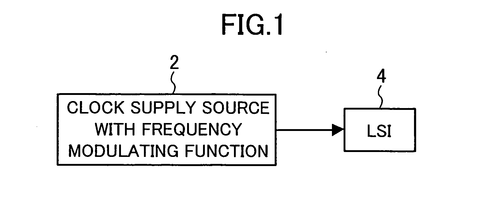
[0026]FIG. 1 is a block diagram illustrating a circuit according to an embodiment of the present invention. The circuit of FIG. 1 comprises a clock supply source 2 which has a frequency modulating function, and an integrated circuit (hereinafter referred to as an LSI) 4. The LSI 4 is mounted on a mount board, such as a printed circuit board or the like.

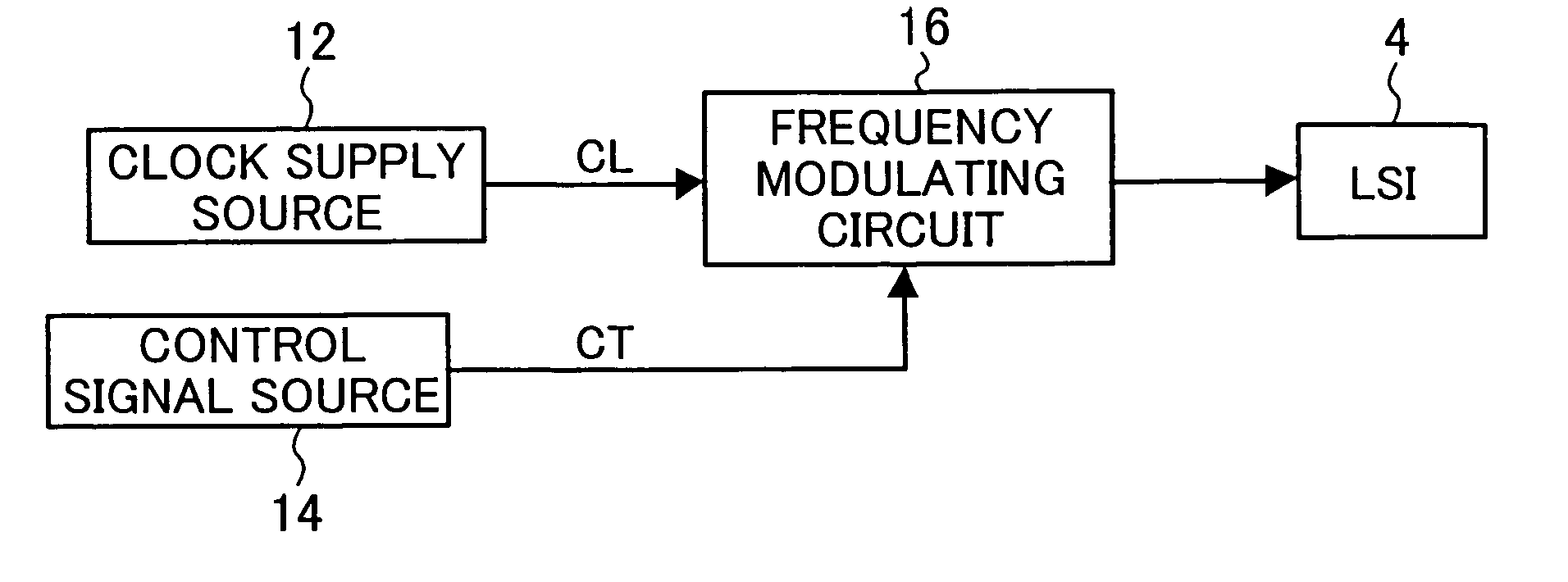
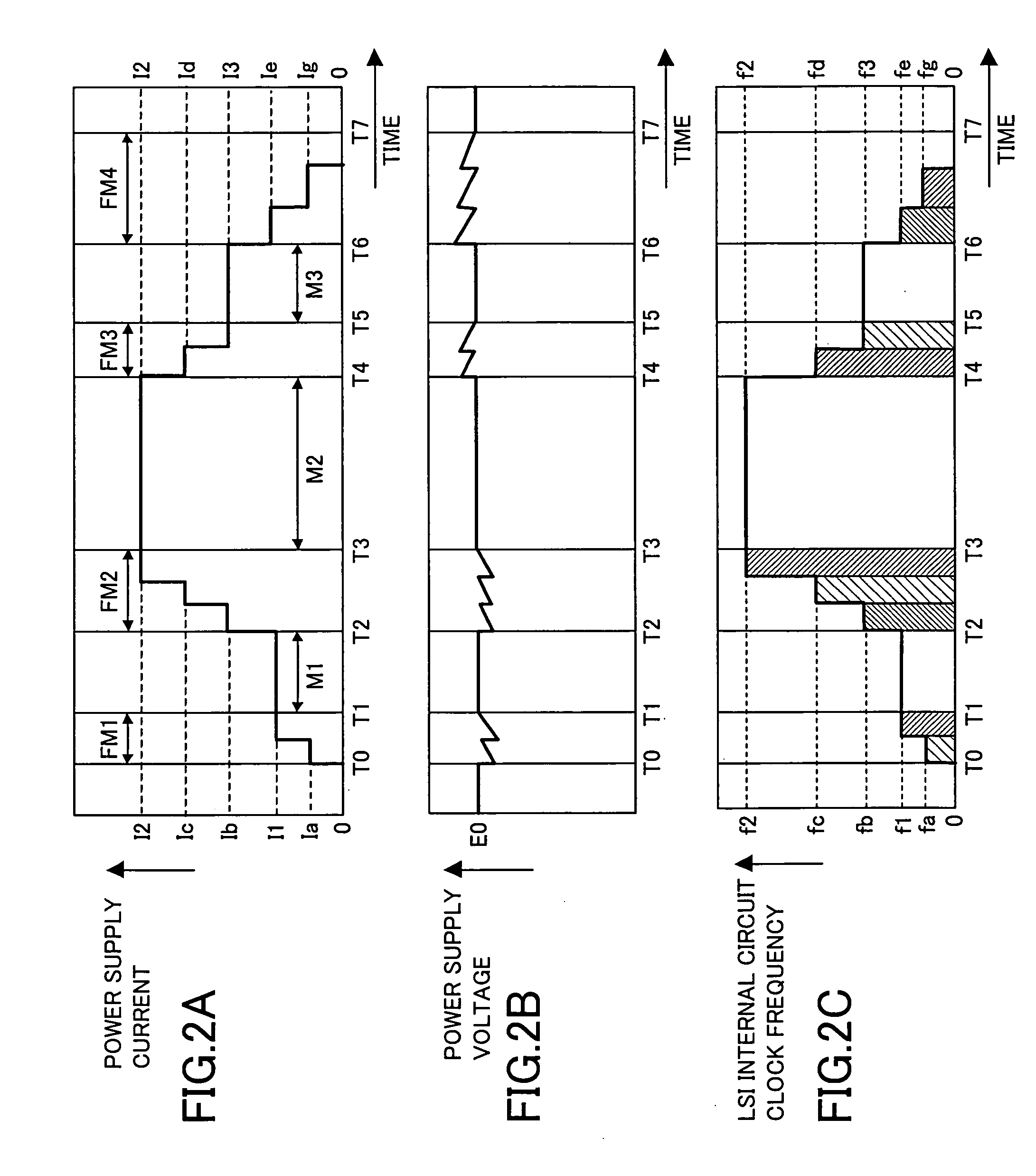
[0027] The LSI 4 is connected to a power supply circuit (not shown), and a voltage E0 is applied from the power supply circuit to the LSI 4 in a normal state. Hereinafter, currents other than one which the power supply circuit supplies to the LSI 4 are not taken into consideration. Under the assumption, a current supplied to the LSI 4 is equal to a power supply current i supplied from the power supply circuit.

[0028]FIGS. 2A to 2C are graphs illustrating an operation of the LSI 4 when operating modes are changed. FI...


PUM


Abstract

A method is provided for controlling an operating frequency of an integrated circuit when operating modes with different operating frequencies are changed. The method comprises the step of changing the operating frequency of the integrated circuit to an operating frequency of an operating mode after changing, in a stepwise manner.

Description

BACKGROUND OF THE INVENTION [0001] The present invention relates to an integrated circuit, and more particularly, to a technique for reducing a steep change in a power supply current when an operating frequency of an integrated circuit is changed. [0002] There is a known technique for suppressing a variation in a power supply voltage during a stable operation of an integrated circuit by regulating a phase of a clock which is supplied to an internal circuit of the integrated circuit (see, for example, JP No. 2004-88638 A). [0003] Thus, the power supply voltage can be stabilized by regulating the phase of the clock which is supplied. However, even with this technique, a power supply current varies when operating modes of an integrated circuit are changed: from a stop state to an operating state; the operating state to the stop state; an operating mode with small power consumption to an operating mode with large power consumption; or the operating mode with large power consumption to t...

Claims


Application Information

Patent Timeline
Patent Type & Authority Applications(United States)
IPC IPC(8): G06F1/00G06F1/04G06F1/08H03K3/02H03K7/06
CPCG06F1/08Y02B60/1217G06F1/324G06F1/3203Y02D10/00
Inventor KITANAKA, MASANORI
Owner PANASONIC CORP
Why Eureka
Try Eureka