Main circuit of controllable current disturbing source

A technology of current disturbance and main circuit, applied to electrical components, AC power input conversion to DC power output, output power conversion devices, etc., can solve the problems of small output capacity, weak overload capacity, high cost, etc., to achieve fast response, The effect of low cost and low loss

Inactive Publication Date: 2010-05-19
NORTH CHINA ELECTRIC POWER UNIV (BAODING)
View PDF0 Cites 6 Cited by
  • Summary
  • Abstract
  • Description
  • Claims
  • Application Information

AI Technical Summary

Problems solved by technology

[0004] The purpose of the present invention is to provide a controllable current disturbance source main circuit, which solves the problems of large power consumption, high cost, weak overload capacity, and small output capacity.

Method used


Image

  • Main circuit of controllable current disturbing source
  • Main circuit of controllable current disturbing source

Examples


specific Embodiment approach

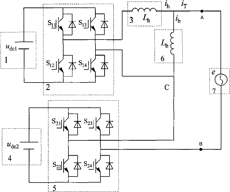
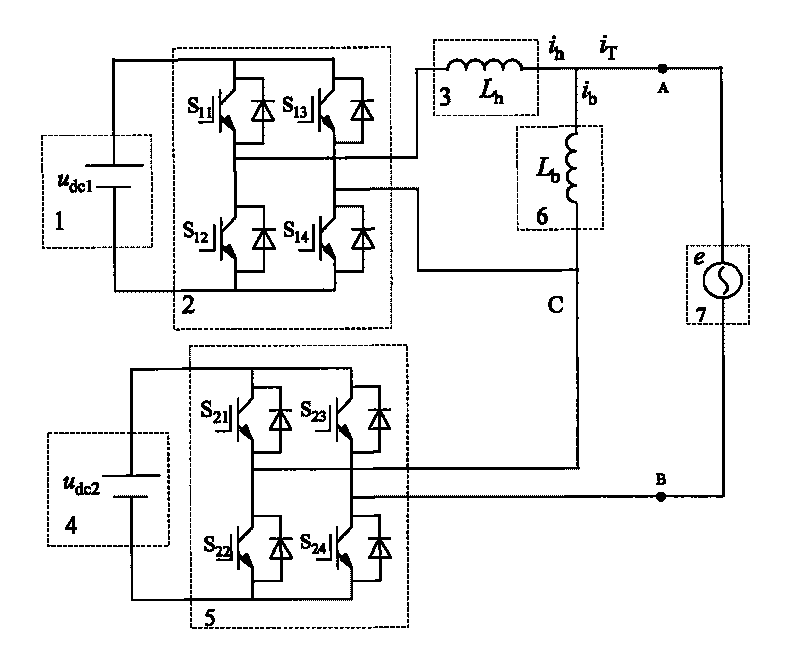
[0010] figure 1 A specific embodiment of the main circuit of a controllable current disturbance source provided by the present invention includes a DC power supply 1, a high-frequency H-bridge inverter 2, a high-frequency reactor 3, a DC power supply 4, and a fundamental frequency H-bridge inverter Transformer 5, fundamental wave reactor 6 and system power supply 7.

[0011] The DC power supply 1 is composed of an electrolytic capacitor, and a high-frequency H-bridge inverter 2 is connected in parallel between the positive pole and the negative pole of the electrolytic capacitor; the high-frequency H-bridge inverter 2 is formed by connecting two IGBT bridge arms in parallel, and each IGBT bridge arm It is composed of two IGBTs connected in series, and the connection points of the IGBTs constitute the two output terminals of the high-frequency H-bridge inverter 2; one output terminal of the high-frequency H-bridge inverter 2 is connected to the input terminal of the high-freque...


PUM


Abstract

The invention discloses a main circuit of a controllable current disturbing source, and belongs to the technical field of power quality disturbance generation. The main circuit of the controllable current disturbing source comprises a direct-current power supply, a high-frequency H bridge inverter, a high-frequency reactor, a direct-current power supply, a base-frequency H bridge inverter, a fundamental wave reactor and a system power supply. The main circuit of the controllable current disturbing source has the advantages of large output capacity, broad current modulation frequency band, quick response, low loss, high reliability and low cost.

Description

technical field [0001] The invention belongs to the technical field of power quality disturbance generation, and in particular provides a controllable current disturbance source main circuit. Background technique [0002] At present, the controllable current sources on the market mainly use linear amplifiers composed of high-power transistors (BJT), field effect transistors (MOS) and other semiconductor devices to complete the output function of the set current, which has the advantages of good control linearity and high precision. . But its inherent defects are also very obvious: (1) The switching device in the main circuit works in the linear amplification area, which consumes a lot of power, generates heat, and the operating point is easily affected by temperature drift; (2) due to the device voltage and current capacity However, this type of controllable current source is difficult to output high power and can only be used in some low-power applications. [0003] The i...

Claims


Application Information

Patent Timeline
Patent Type & Authority Applications(China)
IPC IPC(8): H02M7/5387
Inventor 刘乔尹忠东单任仲肖湘宁洪秋戴成昕孔舒红
Owner NORTH CHINA ELECTRIC POWER UNIV (BAODING)
Why Eureka
Try Eureka