
A Differential Positioning Seismograph While Drilling

A differential positioning and seismograph technology, applied in seismology for well logging records, etc., can solve problems such as inconvenient construction on site, unguaranteed trace spacing and offset, and trace spacing errors, etc., to ensure accuracy and guarantee Measurement accuracy and the effect of reducing seismic interpretation errors

Active Publication Date: 2011-12-21
中石化石油工程技术服务有限公司 +1
View PDF0 Cites 0 Cited by
  • Summary
  • Abstract
  • Description
  • Claims
  • Application Information

AI Technical Summary

Problems solved by technology

[0005] The analog and digital components of most of the seismic recording systems in the prior art are designed separately, and external wiring is required to connect the analog components of one or several units of the geophone with the digital recording unit and the telemetry component, which brings many problems to the construction site. inconvenient
The operation of the digital recording unit and the telemetry unit and the seismic sensors are pre-programmed and cannot be controlled and monitored in real time
[0006] Ordinary seismographs design the location of the geophone group through experiments before exploration, and calculate the corresponding track spacing and offset distance. The offset cannot be guaranteed to be consistent with the calculated value, and the error of trace spacing directly affects the interpretation work of seismic while drilling
In addition, the dip angle change of the geophone group is also an important factor affecting the accuracy of seismic exploration, and the current seismograph cannot realize real-time monitoring of this information

Method used


Image

  • A Differential Positioning Seismograph While Drilling
  • A Differential Positioning Seismograph While Drilling
  • A Differential Positioning Seismograph While Drilling

Examples


Embodiment Construction

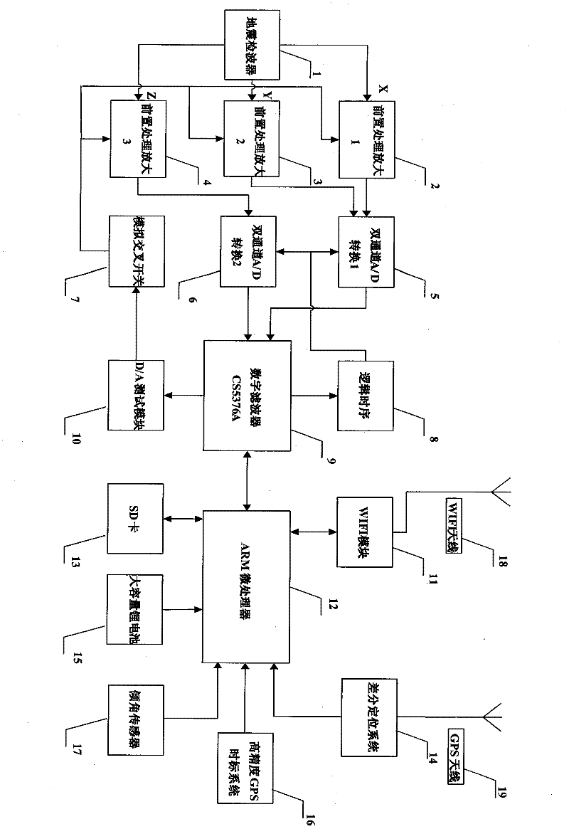
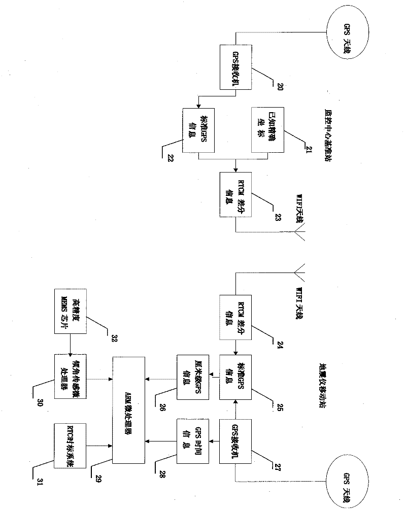
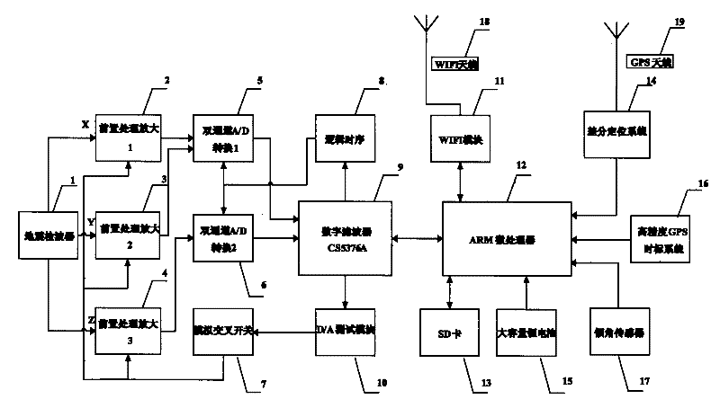
[0019] Now combined with the manual figure 1 And attached figure 2 , to further describe the present invention.

[0020] figure 1 It shows the circuit diagram of the differential positioning while drilling seismograph. The geophone (1) collects the vibration signal reflected in front of the drill bit, outputs X, Y, and Z three-channel analog components, respectively passes through the pre-processing amplification module, enters the dual-channel A / D conversion chip, and outputs digital signals to the digital filter CS5376A (9), after setting multi-stage filtering, be connected to ARM microprocessor (12) by SPI bus line and process. In order to ensure the stability of the seismic signal processing, the D / A test module (10) is controlled by the output of the digital filter CS5376A to replace the output of the geophone (1) with an analog signal of a known frequency range, so as to detect each component of the entire acquisition circuit. Item indicators and characteristics. T...


PUM


Abstract

The object of the present invention is to provide a differential positioning seismometer while drilling that meets the requirements of seismic measurement while drilling. During the drilling process, the seismometer uses a geophone to measure the seismic reflection waves generated by the drill bit hitting the formation, and the measured seismic waves It is converted into a digital signal and combined with the position information generated by the differential positioning system, the time information generated by the high-precision GPS time scale system and the vertical information of the geophone generated by the inclination sensor to form the seismic data during the drilling process, which is composed of data transmission modules The wireless local area network of the drilling well site realizes the high-speed real-time transmission of the above data. The device can collect fixed-point and timing seismic waves in the seismic system while drilling in real time without lag, and realize high-precision differential positioning of the collection points. The computer in the monitoring center can display the survey line, accurately calculate the trace spacing and offset, and reduce the seismic interpretation error. , while using the inclination sensor to monitor the inclination change of the geophone in real time.

Description

technical field [0001] The invention is aimed at the development of new technology of exploration while drilling in the field of seismic exploration, and is also applicable to the fields of petroleum, geology, coal and other exploration fields. It is based on a high-precision differential positioning system and can realize a new generation of high-performance real-time seismic with virtual survey lines. data collection system. Background technique [0002] Vertical seismic profiling (VSP) is an effective method of side-hole seismic exploration. In order to obtain the vertical seismic profile near the well, the drilling process needs to be interrupted during VSP data acquisition, and a downhole geophone is placed in the well, and the measurement is carried out by exciting the ground source. Because of the risks associated with operating in an open hole, VSP measurements are usually performed after cementing. VSP measurement is carried out when drilling reaches a certain sta...

Claims


Application Information

Patent Timeline
Patent Type & Authority Patents(China)
IPC IPC(8): G01V1/42
Inventor 韩来聚魏茂安孙正义许海庭曹忠成李玉红王爱凤于笑冬
Owner 中石化石油工程技术服务有限公司
Learn More