Electronic device, control system and method for controlling light-emitting components thereof

A technology for light-emitting components and control systems, applied in the field of control systems, can solve problems such as inability to know information, inability to adjust the brightness of LED indicators, and user confusion.

Active Publication Date: 2012-06-27
WISTRON CORP
View PDF0 Cites 0 Cited by
  • Summary
  • Abstract
  • Description
  • Claims
  • Application Information

AI Technical Summary

Problems solved by technology

[0003] However, in the prior art, the light-emitting diode indicator light arranged on the notebook computer may cause interference in some environments
For example, in a conference room or in an airplane cockpit, excessively bright lights may cause distress to the user or others
Nowadays, the control of LED indicator lights is almost only on and off, and users cannot adjust the brightness of LED indicators.
If the LED indicator light is completely turned off, it may prevent the user from knowing some important information, such as the battery level or the status of the wireless network

Method used


Image

  • Electronic device, control system and method for controlling light-emitting components thereof
  • Electronic device, control system and method for controlling light-emitting components thereof
  • Electronic device, control system and method for controlling light-emitting components thereof

Examples


Embodiment Construction

[0022] In order to make the above and other objects, features and advantages of the present invention more comprehensible, specific embodiments of the present invention are listed below and described in detail in conjunction with the accompanying drawings.

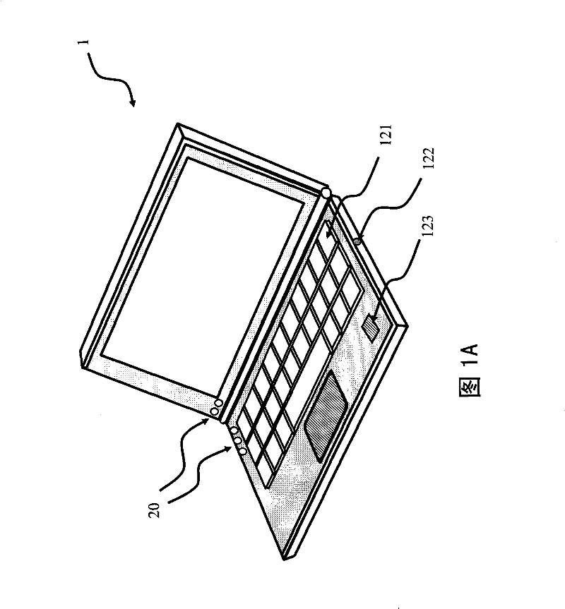
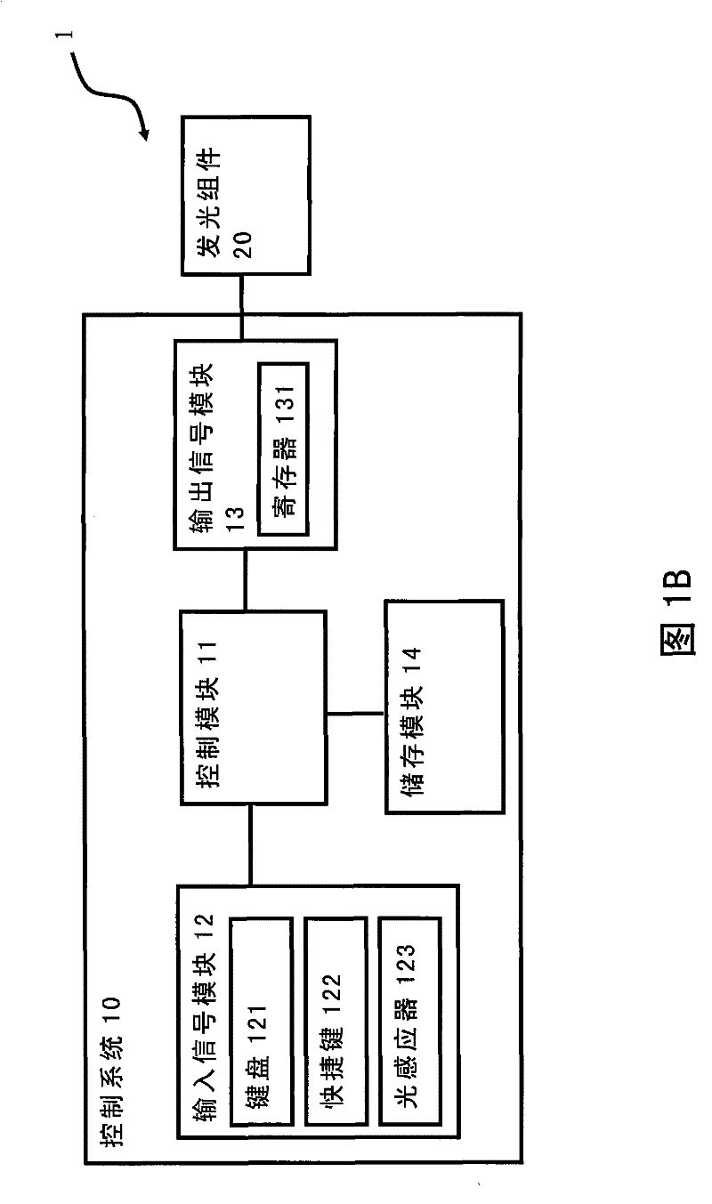
[0023] Please also refer to Figure 1A and Figure 1B . Figure 1A It is a schematic diagram of the appearance of the electronic device of the present invention, Figure 1B It is the internal structure diagram of the electronic device of the present invention.

[0024] The electronic device 1 can be a notebook computer or a mobile phone, but the present invention is not limited thereto. In this embodiment, a notebook computer is taken as an example for description. The electronic device 1 includes a control system 10 and a light emitting component 20 . The control system 10 of the present invention is set in the electronic device 1 to control the light-emitting component 20 installed in the electronic device 1, wherein ...


PUM


Abstract

The invention relates to an electronic device, a control system and a method for controlling light-emitting components thereof. Specifically, the electronic device comprises the light-emitting components and the control system. The control system is used for controlling the light-emitting components. The control system comprises a control module, an input signal module and an output signal module, wherein the input signal module is electrically connected with the control module and is used for inputting a signal; and the output signal module is electrically connected with the control module and is used for outputting a control signal. When the input signal module inputs the signal, the control module utilizes the signal to control the output signal module to send out the control signal soas to adjust the brightness of the light-emitting components. The method for controlling the light-emitting components comprises the following steps of: determining whether the signal is input by adopting the control system; if so, adjusting the set of a register according to the signal; outputting the control signal; and adjusting the brightness of the light-emitting components according to the control signal. The electronic device can adjust the brightness of the light-emitting components at any time, and does not only have two conditions of full on and full off.

Description

technical field [0001] The invention relates to a control system and method, in particular to a system and method capable of adjusting the brightness of a light-emitting component of an electronic device. Background technique [0002] With the advancement of technology, today's electronic devices such as notebook computers have become more and more popular. Users' requirements for notebook computers are not limited to their functions, and the appearance of notebook computers is also one of the key points when selecting notebook computers. Nowadays, it is very common for notebook computers to use the brightness of the light-emitting diodes to represent the status of the system, for example, to indicate the power of the battery or the status of the wireless network. On the other hand, there are also notebook computers that use the appearance of the light-emitting diode indicator light to achieve the purpose of decoration. [0003] However, in the prior art, the light-emittin...

Claims


Application Information

Patent Timeline
Patent Type & Authority Patents(China)
IPC IPC(8): G06F1/16H05B37/02
CPCY02B20/42Y02B20/40
Inventor 顾育先
Owner WISTRON CORP
Why Eureka
Try Eureka