Electronic mail box system
A mailbox and alarm system technology, applied in the direction of electrical program control, program control in sequence/logic controller, other household appliances, etc.
- Summary
- Abstract
- Description
- Claims
- Application Information
AI Technical Summary
Problems solved by technology
Method used
Image

Examples
Embodiment Construction
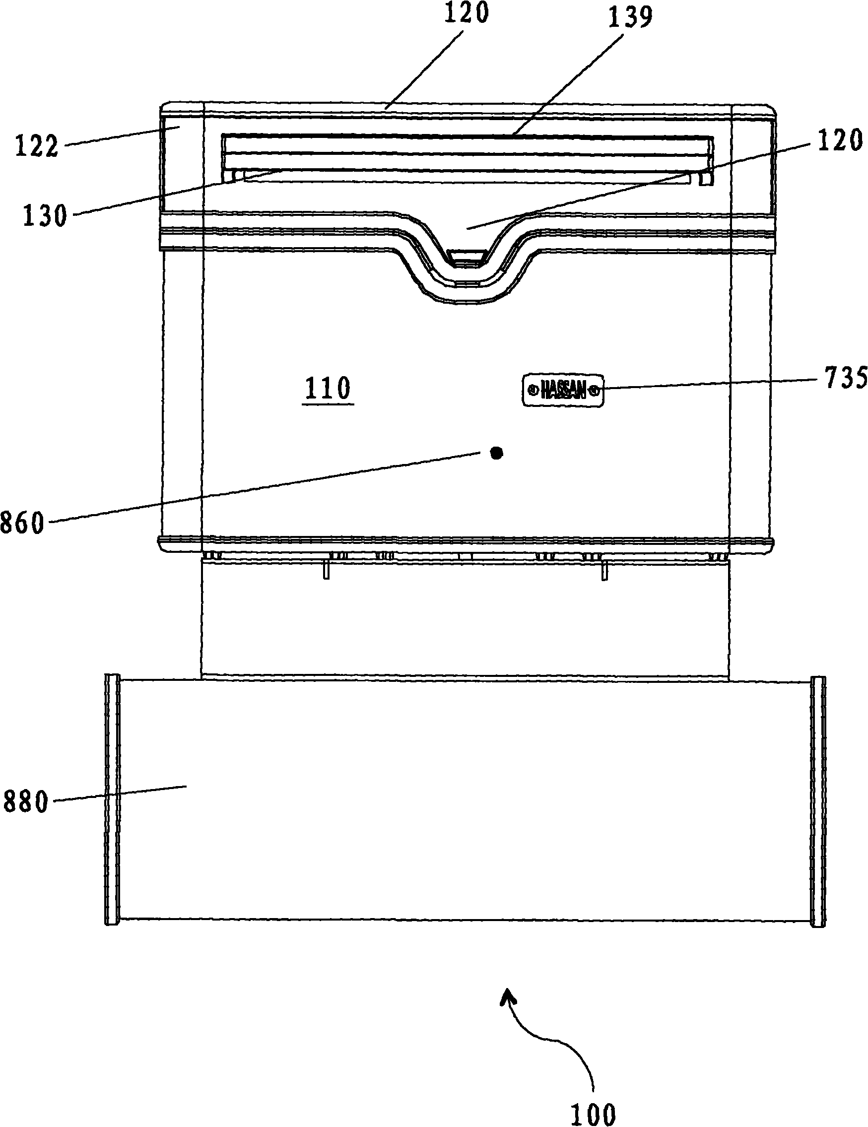
[0036] see now Picture 1-1 7. The present invention is characterized by an electronic mailbox system 100 for providing a secure environment for receiving mail.
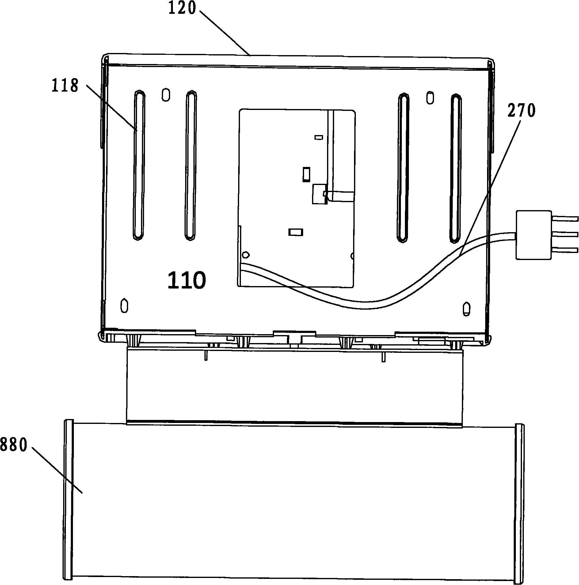
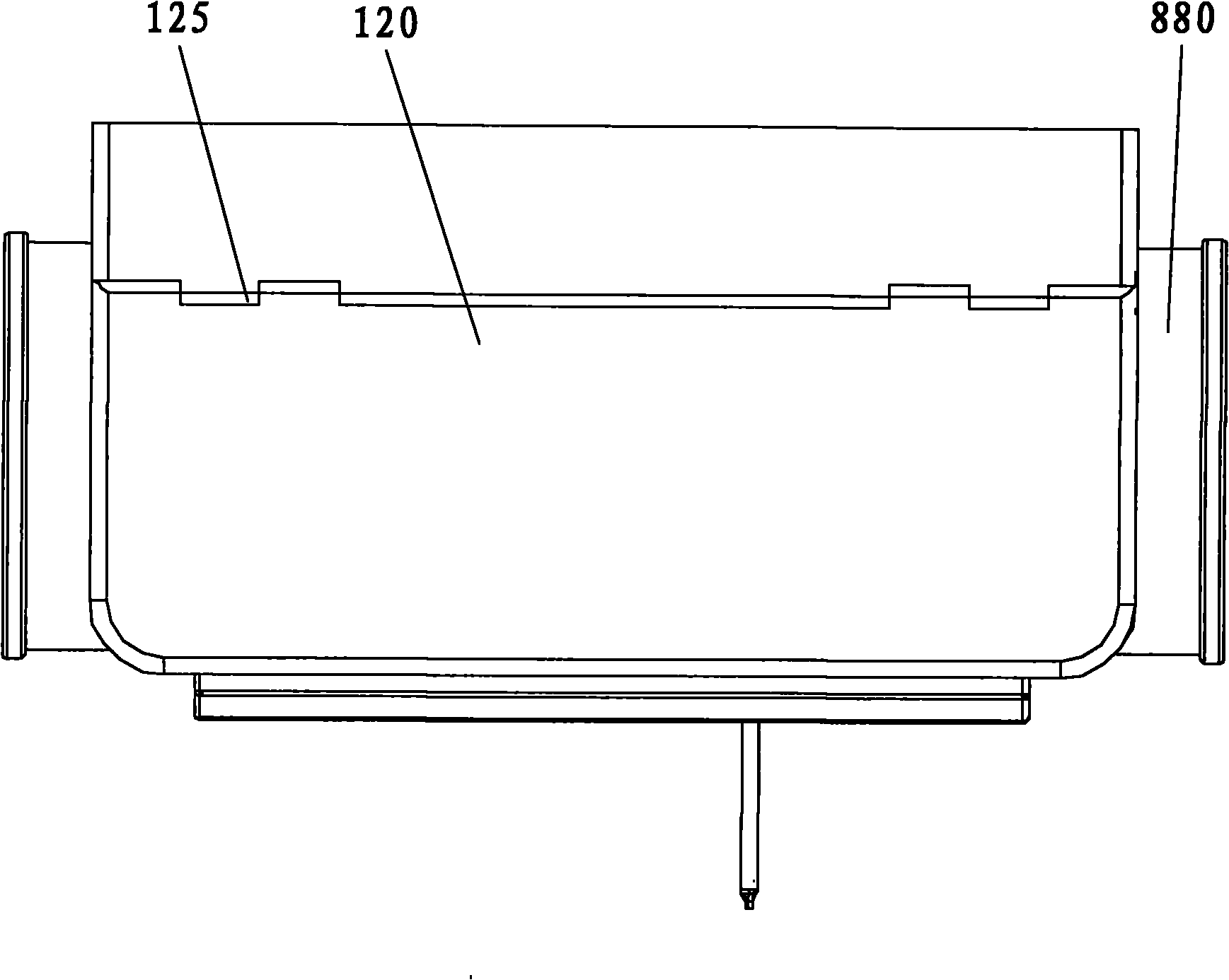
[0037] Such as figure 1 As shown, the electronic letterbox system 100 includes a letterbox housing 110 having a first side, a second side, a front surface, a back surface, a bottom surface, and an interior cavity for receiving letters. A top cover 120 (eg, an "exit door") is pivotally connected to the letterbox housing 110 (eg, back surface, top surface). The top cover 120 (eg, an "exit door") is movable between an open position and a closed position that allow and prevent access to the interior cavity of the letterbox housing 110, respectively.
[0038] In some embodiments, the newspaper holder 880 is disposed on the letterbox housing 110 , such as on a bottom surface (or other portion) of the letterbox housing 110 . A newspaper may be attached to or inserted into the newspaper holder 880 .
[0039]The front su...
PUM
 Abstract
Description
Claims
Application Information
PatSnap Eureka turns technology decisions into work you can execute. Powered by our Innovation Knowledge Graph, it runs expert workflows across engineering, life sciences, materials and intellectual property. Get your review-ready output in minutes.


