Optical fiber dispersion measurement system and use method thereof

A technology for measuring system and optical fiber dispersion, which is applied in the direction of testing optical performance, etc., and can solve problems such as not being able to meet the requirements of photonic crystal fiber

Active Publication Date: 2010-09-01
NAT UNIV OF DEFENSE TECH
View PDF4 Cites 24 Cited by
  • Summary
  • Abstract
  • Description
  • Claims
  • Application Information

AI Technical Summary

Problems solved by technology

Therefore, the traditional white light interference dispersion measurement method still cannot meet the needs of practical application of photonic crystal fiber

Method used


Image

  • Optical fiber dispersion measurement system and use method thereof
  • Optical fiber dispersion measurement system and use method thereof
  • Optical fiber dispersion measurement system and use method thereof

Examples


Embodiment

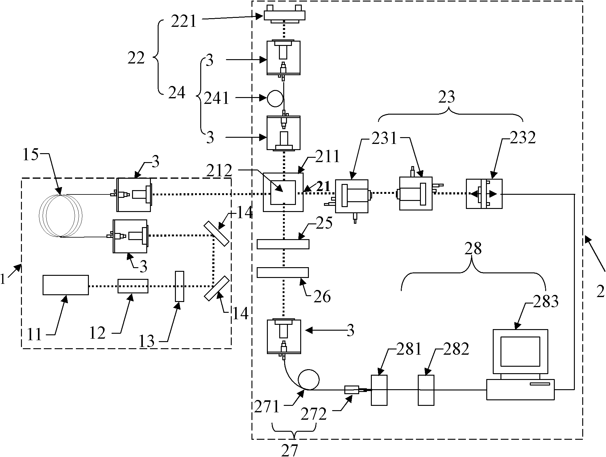
[0046] a kind of like figure 1 The optical fiber dispersion measurement system shown includes a light source system 1 and an interferometric measurement system 2. The light source system 1 includes a pulsed laser 11, an optical isolator 12, a narrow-band filter 13, a reflector group 14, and a light source sequentially arranged along the optical path. Photonic crystal fiber 15, the interferometric measurement system 2 of the present embodiment mainly adopts a Michelson interferometer, including a beam splitter 21, a measuring arm 22 receiving beam splitter 21 reflected beam and a reference arm 23 receiving beam splitter 21 transmitted beam .

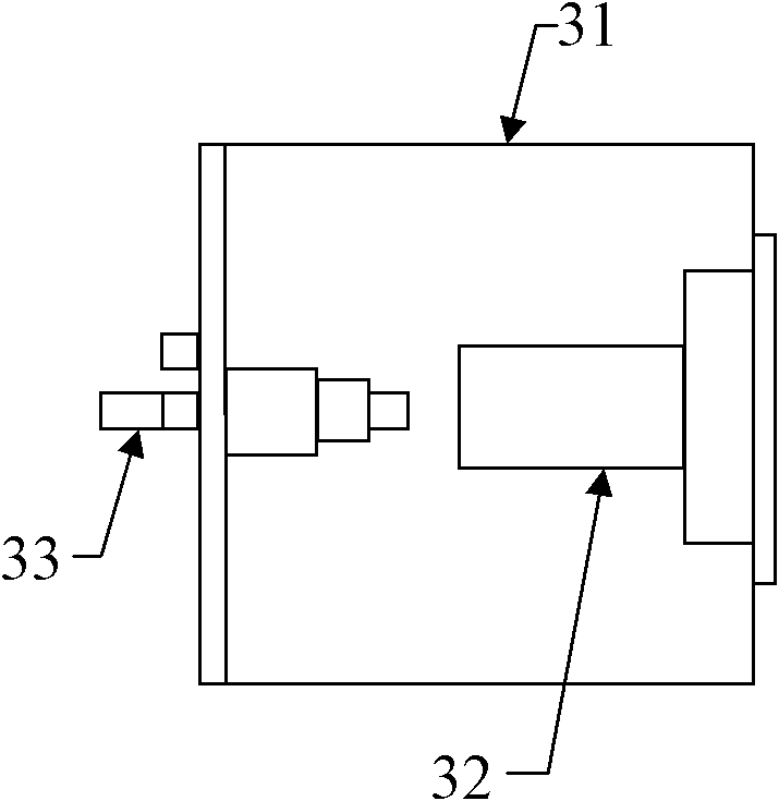
[0047] In the light source system 1, the input end of the photonic crystal fiber 15 for the light source is connected with a three-dimensional fiber coupling platform 3 that receives the reflected light beam of the mirror group 14, and the output end of the photonic crystal fiber 15 for the light source is connected with a collimated inci...


PUM


Abstract

The invention belongs to the field of optical test equipment and a use method thereof and particularly discloses an optical fiber dispersion measurement system which comprises a light source system and an interference measurement system, wherein the light source system comprises a pulse laser, an optical isolator, a narrow band filter slice, a reflector set and a photonic crystal optical fiber for a light source; the pulse laser, the optical isolator, the narrow band filter slice, the reflector set and the photonic crystal optical fiber for the light source are sequentially arranged along an optical path; the interference measurement system comprises a beam splitter, a measurement arm for receiving beams reflected and transmitted by the beam splitter, and a reference arm, and optical fiber assemblies to be measured are arranged in the measurement arm; both ends of the photonic crystal optical fiber for the light source are connected with a three-dimensional optical fiber coupling platform; and the beam splitter is additionally provided with an output end, the optical path arranged behind the output end is sequentially provided with a polarizer, a narrow band filter, an endless single mode photonic crystal optical fiber assembly and a data collection and treatment system. By selecting a highly nonlinear photonic crystal optical fiber with a special ventage structure as the photonic crystal optical fiber for the light source, the system can generate super-continuum spectrum white lights so as to measure a dispersion coefficient with high accuracy, high efficiency and low cost.

Description

technical field [0001] The invention relates to an optical testing device and its usage method, in particular to a device for measuring the dispersion properties in optics and its usage method. Background technique [0002] Since Russell et al. proposed the concept of photonic crystal fiber in 1992, photonic crystal fiber has attracted great attention of researchers from all over the world due to its unique characteristics, and related theoretical and experimental research papers have been increasing at a rate of 70% every year. The photonic crystal fiber exhibits excellent characteristics such as unlimited single-mode, large mode field area, strong nonlinear effect, high birefringence effect, controllable dispersion, and anomalous dispersion in the visible and near-infrared bands, making it in the dispersion compensation It has great application prospects in aspects such as properties, supercontinuum generation, fiber optic sensing, high-power laser transmission, and high-p...

Claims


Application Information

Patent Timeline
Patent Type & Authority Applications(China)
IPC IPC(8): G01M11/02
Inventor 侯静王泽锋陈胜平陈子伦陈金宝刘泽金姜宗福舒柏宏
Owner NAT UNIV OF DEFENSE TECH
Why Eureka
Try Eureka