Submersible servodrive system

A technology of dragging system and submersible oil, applied in the field of dragging system, can solve the problems of reducing oil production cost, system efficiency, low motor efficiency and power factor, unable to realize flexible control, etc., to achieve effective control, reduce operation cost, attenuation small effect

Inactive Publication Date: 2010-11-03
杭州桐聚科技有限公司
View PDF1 Cites 4 Cited by
  • Summary
  • Abstract
  • Description
  • Claims
  • Application Information

AI Technical Summary

Problems solved by technology

[0003] One is that when it is matched with a centrifugal submersible pump, because the motor speed is lower than the synchronous speed, the motor efficiency and power factor are low;
[0004] Second, when it is matched with the submersible screw pump, the speed is too high to reduce the speed to the speed suitable for the screw pump through the tachometer. Even if the reducer is used, the cost of oil production will be greatly increased and the efficiency of the system will be reduced. The frequency conversion speed control device is used to keep the motor in a low-frequency working state for a long time, and it is easy to cause the temperature rise of the motor to accelerate, causing motor failure
The system cannot realize flexible control, and the efficiency is low
[0005] Third, even if the traditional submersible electric pump system adopts frequency conversion control, its motor control cabinet is often placed on the ground. When the AC power is transmitted to the motor due to long-distance transmission, the energy loss is serious, which further reduces the efficiency of the system.
Although there is still the problem of low energy saving rate when combined with frequency conversion controller

Method used


Image

  • Submersible servodrive system
  • Submersible servodrive system
  • Submersible servodrive system

Examples


Embodiment Construction

[0042] Embodiments of the present invention will be specifically described below in conjunction with the accompanying drawings, so that those skilled in the art can understand and easily implement the present invention.

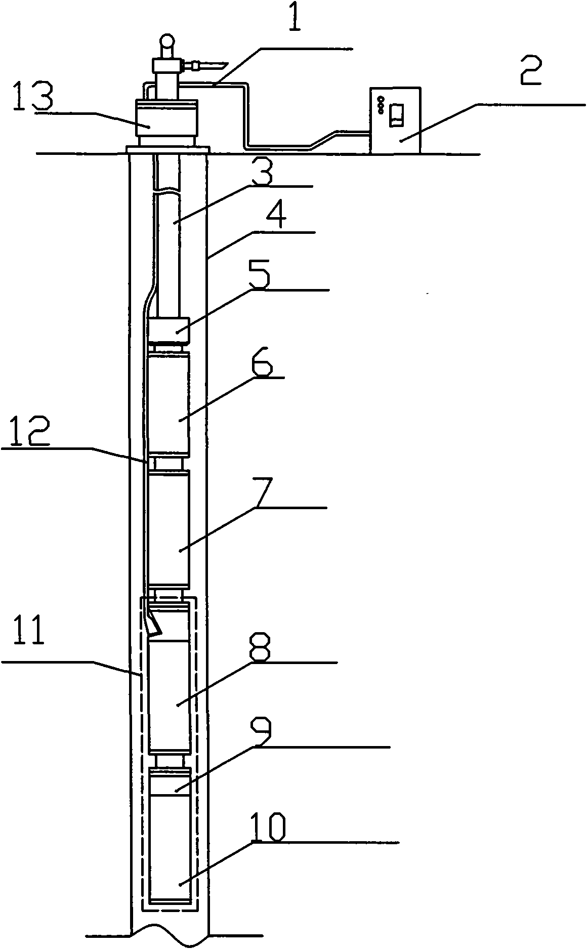
[0043] figure 1 It is a schematic diagram of the installation of the submersible servo pumping system. The submersible electric pump unit is generally placed more than 2,000 meters underground. The entire servo submersible electric pump unit is mainly composed of the ground control box 2, the submersible electric pump 6, the separator (not marked), the protector 7, and the submersible permanent magnet synchronous servo motor. The motor 8, the downhole servo control box, the leading cables 12, 1, etc. are composed, and each part is connected by connecting pieces such as relevant flanges. Other reference numerals represent: tubing 3 , casing 4 , outlet joint 5 , encoder and sealing assembly 9 , submersible servo system 11 and wellhead device 13 . figure 1 The...


PUM


Abstract

A submersible servodrive system comprises a pump and a servo motor system connected with the pump. The system is characterized in that a ground control device is connected with ground power supply by a cable; the cable is connected with the servo motor system; the ground power supply is controlled by the ground control device to supply power to a servo motor and the pump; the servo motor system comprises the servo motor and a servo controller; a motor shaft of the servo motor is provided with a photoelectric coder at the tail; the head of the motor shaft with the photoelectric coder is sealed and stretches into a shell of the servo controller; the photoelectric coder outputs the detected position signal to the servo controller; and the servo controller controls the servo motor to run. The system has high power factor, high energy saving rate and high flexibility, further saves power, can realize flexible production and reduces the operation cost. When being started, a pumping unit can provide large torque, combine with soft start and reduce the power of a matching motor of the pumping unit.

Description

technical field [0001] The invention relates to a drag system, in particular to a submersible servo drag system. Background technique [0002] At present, in my country and other oil-producing countries in the world, submersible motors are widely used in oilfields to drive submersible electric pumps to draw crude oil. The power source of traditional electric submersible pump systems is mainly two-pole three-phase asynchronous motors. There are three problems in the oil recovery system in the process of oil recovery: [0003] One is that when it is matched with a centrifugal submersible pump, because the motor speed is lower than the synchronous speed, the motor efficiency and power factor are low; [0004] Second, when it is matched with the submersible screw pump, the speed is too high to reduce the speed to the speed suitable for the screw pump through the tachometer. Even if the reducer is used, the cost of oil production will be greatly increased and the efficiency of th...

Claims


Application Information

Patent Timeline
Patent Type & Authority Applications(China)
IPC IPC(8): H02P6/00G01D5/249
Inventor 武强赵刚
Owner 杭州桐聚科技有限公司
Why Eureka
Try Eureka