Steel pipe fixture for pipe saw mills

A technology of clamping device and sawing steel pipes, which is applied in the direction of sawing machine, metal sawing equipment, metal processing equipment, etc., can solve the problems of long downward stroke of the saw blade, large vibration and impact, uneven load, etc., and improve the saw blade Longer life, less impact on the saw blade, and less chipping

Inactive Publication Date: 2010-11-10
烟台宝钢钢管有限责任公司
View PDF5 Cites 3 Cited by
  • Summary
  • Abstract
  • Description
  • Claims
  • Application Information

AI Technical Summary

Problems solved by technology

[0005] The purpose of the present invention is to overcome the deficiencies of the above-mentioned prior art, and provide a pipe gang saw steel pipe clamping device, which mainly solves the problem of long saw blade descending stroke, long sawing cycle and load during the cutting process of the existing pipe gang saw. Problems of unevenness, large vibration and impact, and easy chipping

Method used


Image

  • Steel pipe fixture for pipe saw mills
  • Steel pipe fixture for pipe saw mills
  • Steel pipe fixture for pipe saw mills

Examples


Embodiment 1

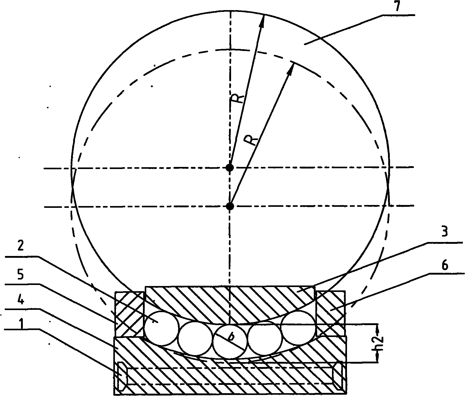
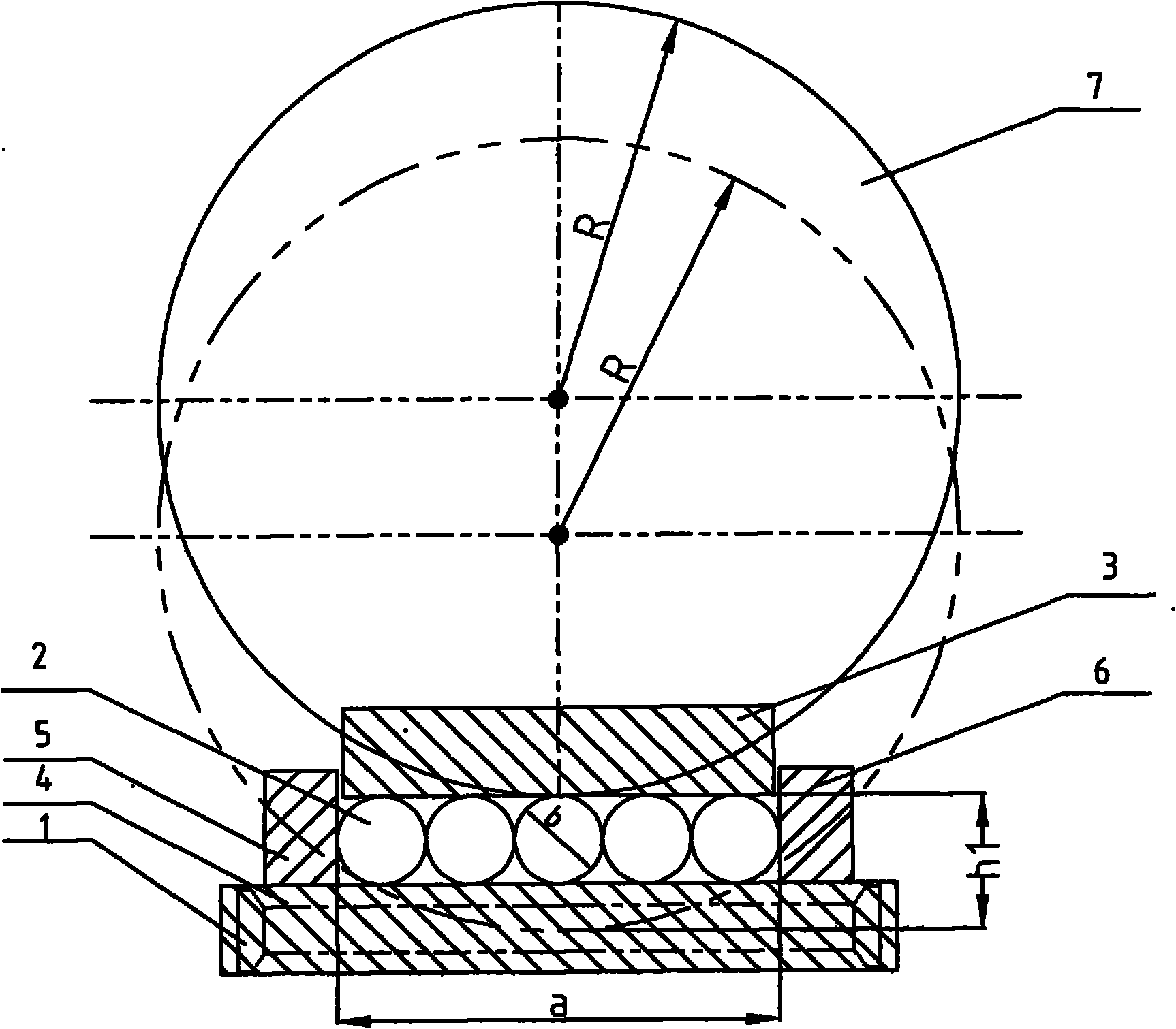
[0013] Example 1: see figure 1 , install a pipe gang saw, select the saw blade 7 radius R is Φ900mm, the diameter b of the cutting steel pipe 2 is Φ200mm, the width of the conveying roller table 1 is 1000mm, 5 steel pipes 2 form a row of simultaneous sawing, and the clamping device consists of The upper splint 3, the lower splint 4, the left splint 5, and the right splint 6 are composed. The surfaces of the upper splint 3 and the lower splint 4 in contact with the steel pipe 2 are arc-shaped, and the two arcs have a common center of circle, and the two concentric arcs The radius difference is the diameter of the clamped steel pipe 4 .

[0014] The process flow is: the conveying roller table 1 conveys the steel pipe 2, and the head of the steel pipe 2 stops when it encounters the positioning baffle; The steel pipe 2 is horizontally centered and clamped; finally, the upper splint 3 descends, and the lower splint 4 clamps the steel pipe 2 on the vertical plane; at this time, the...


PUM


Abstract

The invention discloses a steel pipe fixture for pipe saw mills, which comprises an upper clamping plate (3), a lower clamping plate (4), a left clamping plate (5) and a right clamping plate (6). The steel pipe fixture is characterized in that: the surfaces of the upper clamping plate (3) and the lower clamping plate (4), which are contacted with steel pipes (2), are cambered, moreover, the two cambers are concentric, and the difference between the diameters of the two concentric cambers is the diameter of the clamped steel pipe (2). A saw disk can simultaneously saw each of the steel pipes in a row, the downstroke of the saw disk is shortened, the sawing time is shortened, the sawing efficiency is increased, meanwhile, from the beginning to the end of steel pipe sawing by the saw disk, the area of the row of pipes sawed by the saw disk is nearly unchanged, consequently, the load change of a sawing machine is little, the impact on the saw disk is little, tooth breaking can be reduced, and the service life of the saw disk can be prolonged.

Description

Technical field: [0001] The invention relates to the technical field of production equipment for seamless steel pipes, in particular to a steel pipe clamping device when cutting pipes with a gang saw. Background technique: [0002] In the production of seamless steel pipes, the pipe gang saw is an important seamless steel pipe finishing equipment. Its function is to cut off the uneven wall thickness and outer diameter at both ends of the steel pipe that is longer (about 30-100m) after hot rolling, and divide the steel pipe into steel pipes with different shorter lengths (about 6-14m) according to requirements, so that later processing and transportation. Pipe gang saw is mainly composed of sawing host, conveying roller table, steel pipe positioning baffle, clamping device and so on. The main machine of sawing is to drive the rotating saw blade to cut the steel pipe; the conveying roller is to transport the steel pipe to be cut to the sawing position; the positioning baffle...

Claims


Application Information

Patent Timeline
Patent Type & Authority Applications(China)
IPC IPC(8): B23D47/04
Inventor 王旭午杨为国
Owner 烟台宝钢钢管有限责任公司
Why Eureka
Try Eureka