Method for automatically testing steady state loss torque of flywheel
A technology of steady-state loss and testing method, applied in torque measurement, measuring device, power measurement, etc., can solve the problems that the flywheel cannot simulate the satellite attitude, the flywheel has a large error in steady-state loss torque, etc., and achieves the effect of making up for manual testing
- Summary
- Abstract
- Description
- Claims
- Application Information
AI Technical Summary
Problems solved by technology
Method used
Image

Examples
specific Embodiment approach 1
[0018] Specific implementation mode one: the following combination figure 1 This embodiment will be specifically described. The flywheel automatic steady-state loss torque testing method, the hardware device based on the method is composed of a control computer and a communication board, the control signal input and output terminals of the control computer are connected with the control signal input and output terminals of the communication board, and the communication board's The flywheel control signal input and output terminals are connected to the flywheel control signal input and output terminals of the flywheel;
[0019] Flywheel automatic steady loss torque test method:
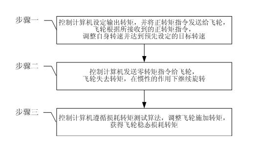
[0020] Step 1. Control the computer to set the output torque, and send the positive torque command to the flywheel, and the flywheel adjusts its own speed according to the received positive torque command to reach the preset target speed;
[0021] Step 2. The control computer sends a zero torque comm...
specific Embodiment approach 2
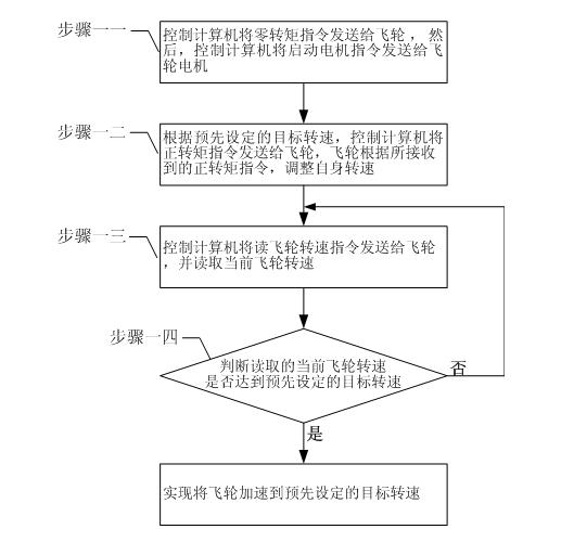
[0029] Specific implementation mode two: the following combination figure 2 This embodiment will be specifically described. This embodiment is a further description of step 1 in the flywheel automated steady-state loss torque test method described in the first specific embodiment. The control computer described in step 1 sets the output torque and sends a positive torque command For the flywheel, according to the positive torque command received by the flywheel, the process of the flywheel motor accelerating the flywheel to the preset speed is:
[0030] Step 11, the control computer sends the zero torque command to the flywheel, and then the control computer sends the start motor command to the flywheel motor;
[0031] Step 12. According to the preset target speed, the control computer sends the positive torque command to the flywheel, and the flywheel adjusts its own speed according to the received positive torque command;
[0032] Step 13, the control computer sends the com...
specific Embodiment approach 3
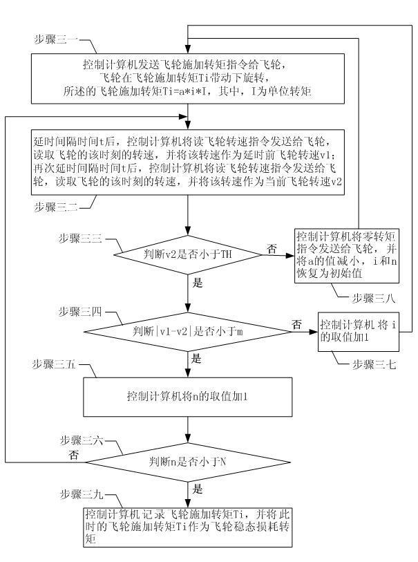
[0034] Specific implementation mode three: the following combination image 3 This embodiment will be specifically described. This embodiment is a further description of step 3 in the flywheel automatic steady-state loss torque test method described in the first and second specific embodiments. The control computer pre-sets the operating parameters in the loss torque test algorithm. Values, including: the coefficient change step size a of the unit torque, and a is a positive number less than or equal to 1, the initial value of the coefficient i of the applied torque of the flywheel is 1, the initial value of the judgment number n is 0, and the maximum speed of the flywheel TH, allowable threshold value m of rotational speed variation, allowable number of repetitions N,
[0035] The control computer described in step 3 follows the loss torque test algorithm, adjusts the applied torque of the flywheel, and the specific process of obtaining the steady state loss torque of the fl...
PUM
 Abstract
Description
Claims
Application Information
 - R&D
- Intellectual Property
- Life Sciences
- Materials
- Tech Scout
- Unparalleled Data Quality
- Higher Quality Content
- 60% Fewer Hallucinations
Browse by: Latest US Patents, China's latest patents, Technical Efficacy Thesaurus, Application Domain, Technology Topic, Popular Technical Reports.
© 2025 PatSnap. All rights reserved.Legal|Privacy policy|Modern Slavery Act Transparency Statement|Sitemap|About US| Contact US: help@patsnap.com