
Comet optical point signal simulation method for deep space exploration

An optical signal and simulation method technology, applied in the field of aerospace navigation, can solve problems such as comet simulation, and achieve the effect of good effect, simple and intuitive drawing, and reliable dynamic optical signal.

Active Publication Date: 2011-11-23
THE PLA INFORMATION ENG UNIV
View PDF0 Cites 0 Cited by
  • Summary
  • Abstract
  • Description
  • Claims
  • Application Information

AI Technical Summary

Problems solved by technology

[0003] At present, many units at home and abroad have successfully developed a star simulator, which satisfies the test and experiment work of using the attitude of the star to measure, but the navigation camera can only obtain the star information for attitude determination. position relative to the target comet, accurate optical information must also be obtained for the target comet
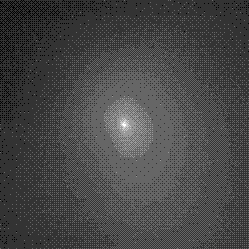
[0004] When the comet is far away from the detector, what the detector observes is the point signal caused by the joint action of the comet nucleus, coma and background brightness. At present, there is no effective method to simulate the point signal of the comet to obtain the target comet’s point signal. Accurate Optical Information

Method used


Image

  • Comet optical point signal simulation method for deep space exploration
  • Comet optical point signal simulation method for deep space exploration
  • Comet optical point signal simulation method for deep space exploration

Examples


Embodiment Construction

[0032] The present invention will be further introduced below in conjunction with specific embodiments:

[0033] 1. Comet optical signal model

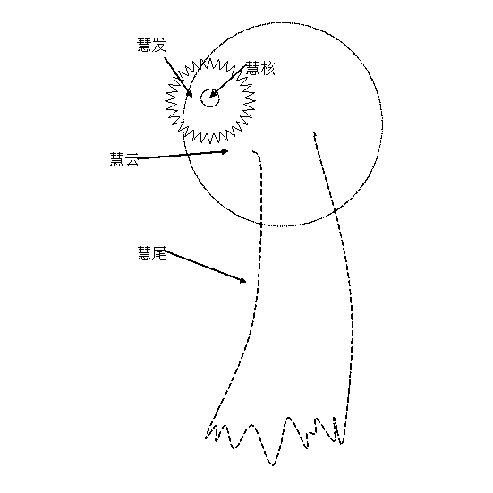
[0034] Such as figure 1 Shown is a schematic diagram of comet morphology. A typical comet morphology includes four parts: nucleus, coma, tail and cloud. The nucleus and the coma are collectively called the head, but only for most comets. Some comets do not necessarily have all four parts, and some do not have a tail or even a coma. It is the same comet whose shape is constantly changing during its orbiting the sun. As it approaches the sun, coma and tail gradually appear; while away from the sun, the coma and tail gradually disappear.

[0035] When the comet is far away from the detector, the detector (with a navigation camera on the detector) observes a point signal that is combined by the comet nucleus, coma, and background brightness. Since the point signal is not just a simple point, it There is also a halo formed by the coma, so it ca...


PUM


Abstract

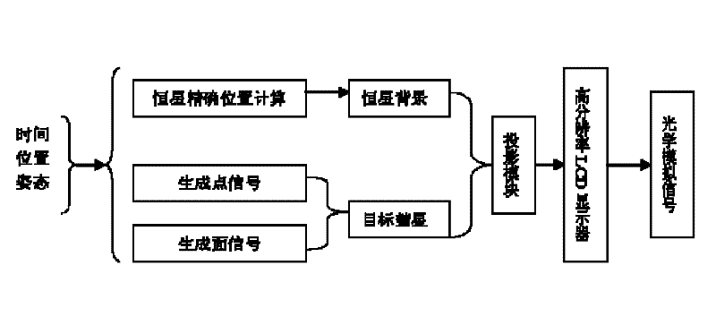
The invention provides a comet optical point signal simulation method for deep space exploration. The method comprises the following steps of: programming by using an OpenGL three-dimensional graphics library to realize simulation of an optical signal; reconstructing a dot signal of the comet by using a particle system and generating a simulation signal of a corresponding direction according to the input time of a simulator, the position of an observation platform and the direction of a camera; projecting the simulation signal on a high-performance display; and completing digital-to-analog conversion of the optical signal on the space and radiance to finally form a simulation optical signal. The method has the advantages of simplicity, intuition, good effect and capability of providing a reliable dynamic optical signal for an optical navigation camera used in deep space exploration, particularly comet impact detection.

Description

Technical field [0001] The invention belongs to the technical field of space navigation, and in particular relates to a comet optical signal simulation method for deep space detection. Background technique [0002] In 2005, the "Impactor" launched by the US "DeepImpact" spacecraft successfully impacted the "Tempel1" comet, which opened the prelude to the exploration of human impacts on comets. The optical navigation in this collision detection is an important guarantee for the impactor to accurately hit the target. In optical navigation, whether it is the test of the navigation camera or the verification of the data processing scheme in the optical navigation, it is inseparable from the starry sky and the target comet. Optical signal. Before the detector actually takes real images of the starry sky and the target comet, the only way to obtain the optical signal is the simulation in the ground laboratory environment. [0003] At present, many units at home and abroad have successfu...

Claims


Application Information

Patent Timeline
Patent Type & Authority Patents(China)
IPC IPC(8): G01C21/00
Inventor 徐青蓝朝桢施群山邢帅马东洋李建胜周杨孙伟张衡何钰靳国旺龚志辉
Owner THE PLA INFORMATION ENG UNIV
Learn More