Portable air compressor

A technology for air compressors and compression units, which is applied in the field of air compressors and can solve problems such as lowering work efficiency and increasing costs

Active Publication Date: 2011-01-12
TECHTRONIC POWER TOOLS TECHNOLOGY LTD
View PDF8 Cites 6 Cited by
  • Summary
  • Abstract
  • Description
  • Claims
  • Application Information

AI Technical Summary

Problems solved by technology

Air tool users lose productivity by walking to the air compressor and back to the job

Method used


Image

  • Portable air compressor
  • Portable air compressor
  • Portable air compressor

Examples


Embodiment Construction

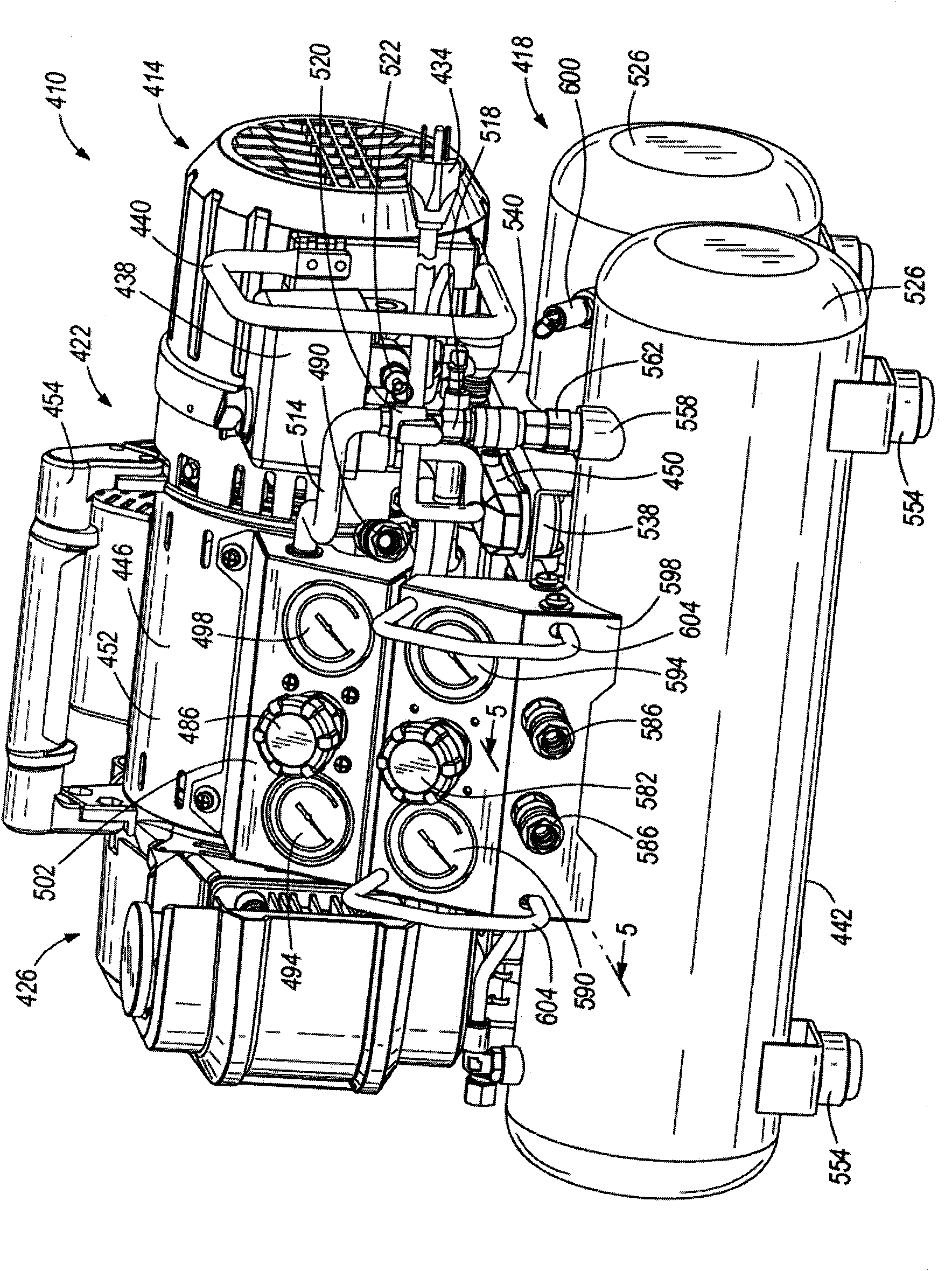
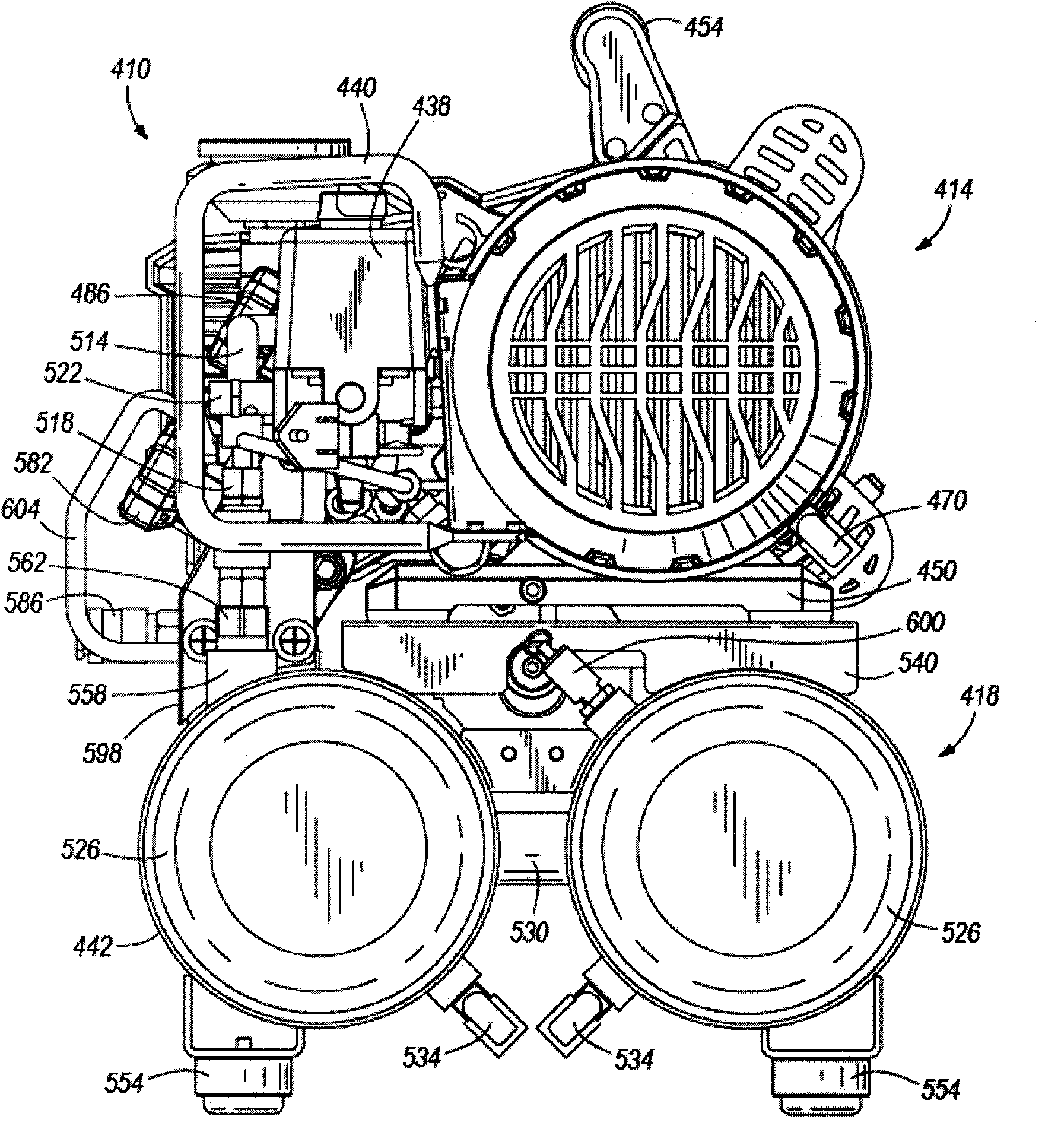
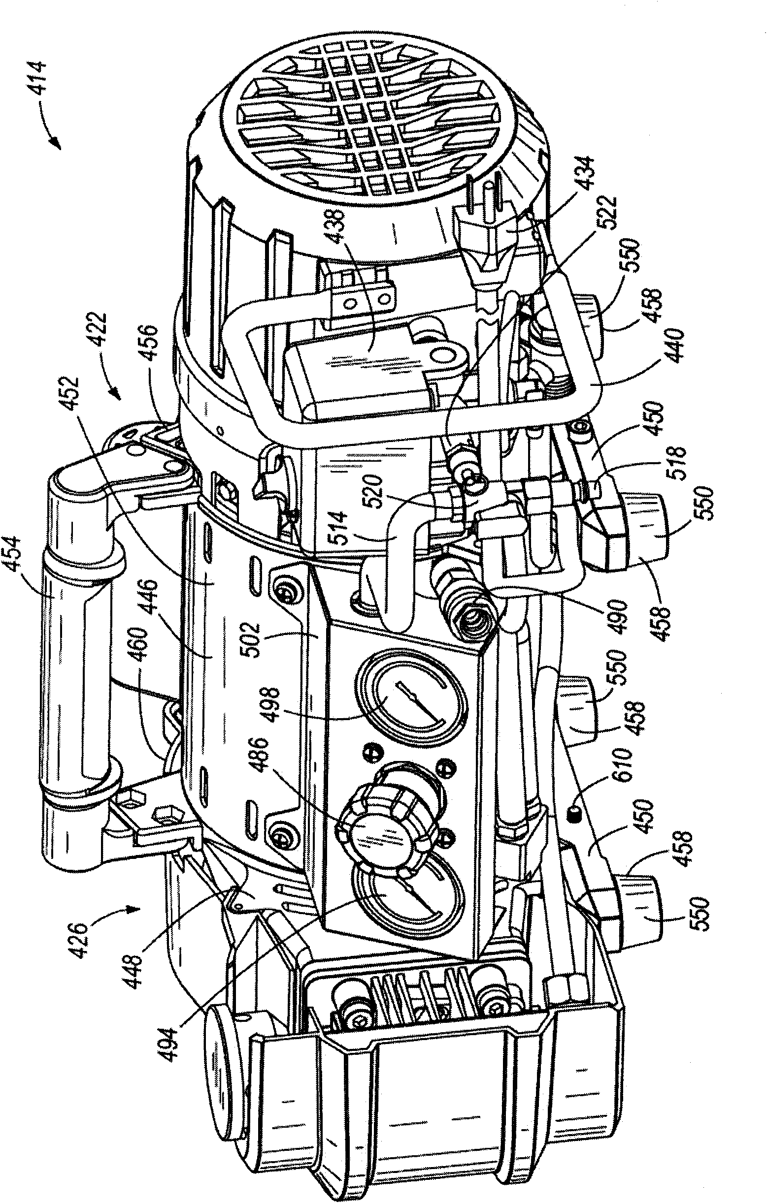
[0022] figure 1 A portable air compressor 410 is shown comprising a pump or compression unit 414 removably connected to a tank unit 418 in a stacked fashion. In the illustrated configuration of air compressor 410 , compression unit 414 is stacked on top of tank unit 418 such that the weight of compression unit 414 is supported by tank unit 418 . Alternatively, the air compressor 410 may be configured with the storage tank unit 418 stacked on top of the compression unit 414 such that the weight of the storage tank unit 418 is supported by the compression unit 414 . Stacking the compression unit 414 and the tank unit 418 in such a manner enables each unit 414, 418 to perform a support or load bearing function that would otherwise be performed by a separate frame for each unit 414, 418. Specifically, when the compression unit 414 and the storage tank unit 418 are stacked and carried as a unit, the compression unit 414 carries the weight of the storage tank unit 418, while when t...


PUM


Abstract

The invention relates to an air compressor. The air compressor comprises a compression unit provided with a motor with a motor housing, a pump operably connected with the motor, and a first storage tank fluidly connected with the pump. The pump is provided with a pump housing internally formed with a part of the motor housing; and the first storage tank receives the compressed air from the pump when the pump is operated by the motor. The air compressor further comprises a storage unit detachably connected with the compression unit in overlapped manner. The storage unit comprises a second storage tank fluidly connected with the pump; and the second storage tank receives the compressed air from the pump when the pump is operated by the motor.

Description

[0001] Cross References to Related Applications [0002] This application claims priority to co-pending US Provisional Patent Application No. 61 / 176,798 filed May 8, 2009, the entire contents of which are hereby incorporated by reference. technical field [0003] This invention relates to air compressors, and more particularly, to portable air compressors. Background technique [0004] Air compressors are commonly used to provide compressed air for operating pneumatic tools such as nailing tools, ferrule driving tools, material forming tools, sanding tools, etc. Typically, air compressors are often located remotely from accompanying air tools that use the compressed air generated by the compressor due to a number of constraints including size, weight, and a source of electrical power suitable for operating the air compressor. Thus, a considerable length of hose is usually required to connect the air compressor to the air tool. Using stretched or long hoses often creates an...

Claims


Application Information

Patent Timeline
IPC IPC(8): F04B41/02
Inventor 塔库·欧西J·耶扎贝克K·M·布拉泽尔W·E·萨德科夫斯基R·L·斯特拉克D·里特林
Owner TECHTRONIC POWER TOOLS TECHNOLOGY LTD
Why Eureka
Try Eureka