Catheter delivery device

A technology for delivery devices and catheters, used in catheters, medical science, stents, etc.

Active Publication Date: 2011-05-04
ANGIOMED GMBH & CO MEDIZINTECHNIK KG
View PDF6 Cites 12 Cited by
  • Summary
  • Abstract
  • Description
  • Claims
  • Application Information

AI Technical Summary

Problems solved by technology

Clearly, it is challenging to include a delivery zone somewhere along the length of the catheter

Method used


Image

  • Catheter delivery device
  • Catheter delivery device
  • Catheter delivery device

Examples


Embodiment Construction

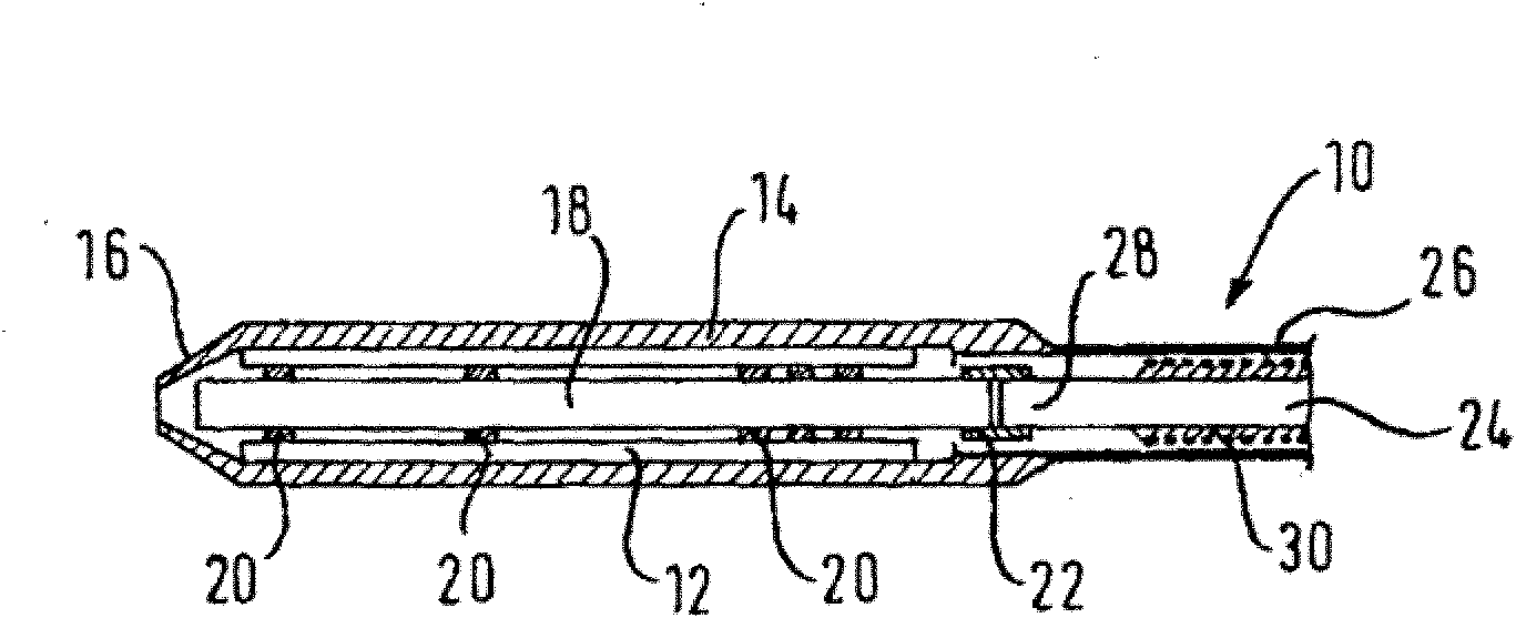
[0027] The delivery system 10 shown is used to deliver a stent graft 12, in figure 1 The stent-graft can be seen compressed inside the distal sheath 14 with the atraumatic tapered distal tip 16 . The stent is a self-expanding stent that presses against the radially inner cylindrical surface of the outer sheath 14 . Inside the radially compressed stent 12 is a stent support tube 18 that defines a guidewire lumen (in figure 1 not visible in ) and carries a plurality of annular gaskets 20 on its outer cylindrical surface. For covered stent-grafts longer than 100 mm, we recommend three of these liners near the proximal end of the stent, one at the distal end of the stent, and one midway along the length of the stent. For shorter stents, a pad halfway along the stent is likely not needed. The pads are manufactured from DYMAX material and may each have a length along the axis of the stent in the range of 2mm to 4mm. Depending on how the liner is attached to the support tube 18, ...


PUM


Abstract

A catheter delivery device for a self-expanding stent including a distal catheter component, a distal sheath disposed over the stent, a proximal catheter shaft defining a tube; a proximal sheath connected to the distal sheath defining a lumen containing the catheter shaft, an open distal end suitable to receive the proximal end of the distal catheter component side-by-side with the distal end of the catheter shaft and; a casing tube surrounding the catheter shaft having a distal end telescopically receiving the proximal end of the distal sheath.

Description

technical field [0001] The present invention relates to a catheter which is a delivery device for a self-expanding stent to be delivered transluminally to a standoff site in the body. The device is "wire-drawn" and is designed to deliver covered stent-grafts of significant length, which represent a more difficult delivery task than short bare stents. The devices described below are of the "over the wire" type. However, the invention may also be applied to "rapid exchange" catheter delivery devices. Guidewire diameters of 18 or 35 "thou" are conventional and contemplated for use with the present invention. Stent-grafts with deployed diameters in the range of 6 mm to 18 mm are contemplated. Background technique [0002] The applicant has progressively developed delivery devices for stent grafts. An example can be found in WO2005 / 053574. The present invention carries forward such constructions into the technical field of stent-grafts which are longer (possibly up to 120mm,...

Claims


Application Information

Patent Timeline
IPC IPC(8): A61F2/84A61F2/95
CPCA61F2/95A61M25/0052A61F2/962
Inventor J·多恩
Owner ANGIOMED GMBH & CO MEDIZINTECHNIK KG
Why Eureka
Try Eureka