Transport roller

A technology of conveying rollers and rollers, which is applied to conveyor objects, rollers, transportation and packaging, etc., can solve problems such as substrate damage and the inability of the rudder to provide electrical contacts.

Inactive Publication Date: 2011-06-01
WUXI SUNTECH POWER CO LTD
View PDF6 Cites 22 Cited by
  • Summary
  • Abstract
  • Description
  • Claims
  • Application Information

AI Technical Summary

Problems solved by technology

However, misalignment between the upper and lower roll rudders can cause damage to the substrate
Also, in electroplating applications, rudder stock usually does not provide a good electrical contact

Method used


Image

  • Transport roller
  • Transport roller
  • Transport roller

Examples


Embodiment Construction

[0029] In the following description, for purposes of explanation, numerous specific details are set forth in order to provide a thorough understanding of the present invention. It will be apparent, however, that embodiments may be made without these specific details. In other instances, well-known structures and devices are shown in block diagram form in order to avoid unnecessarily obscuring the embodiments.

[0030] Example Conveyor Roller

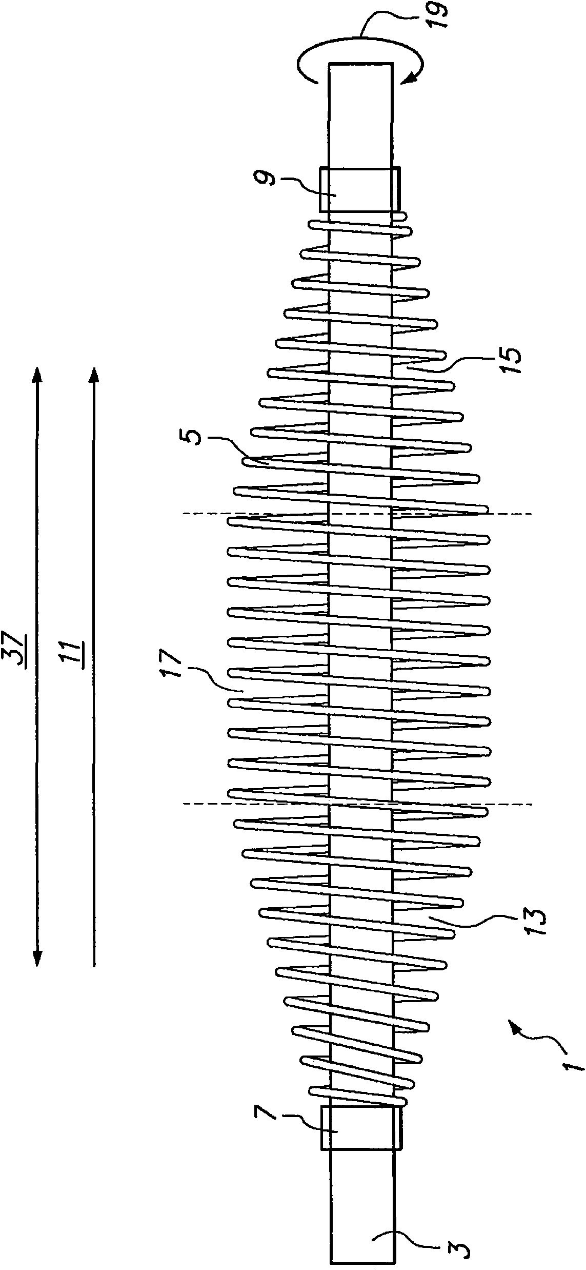
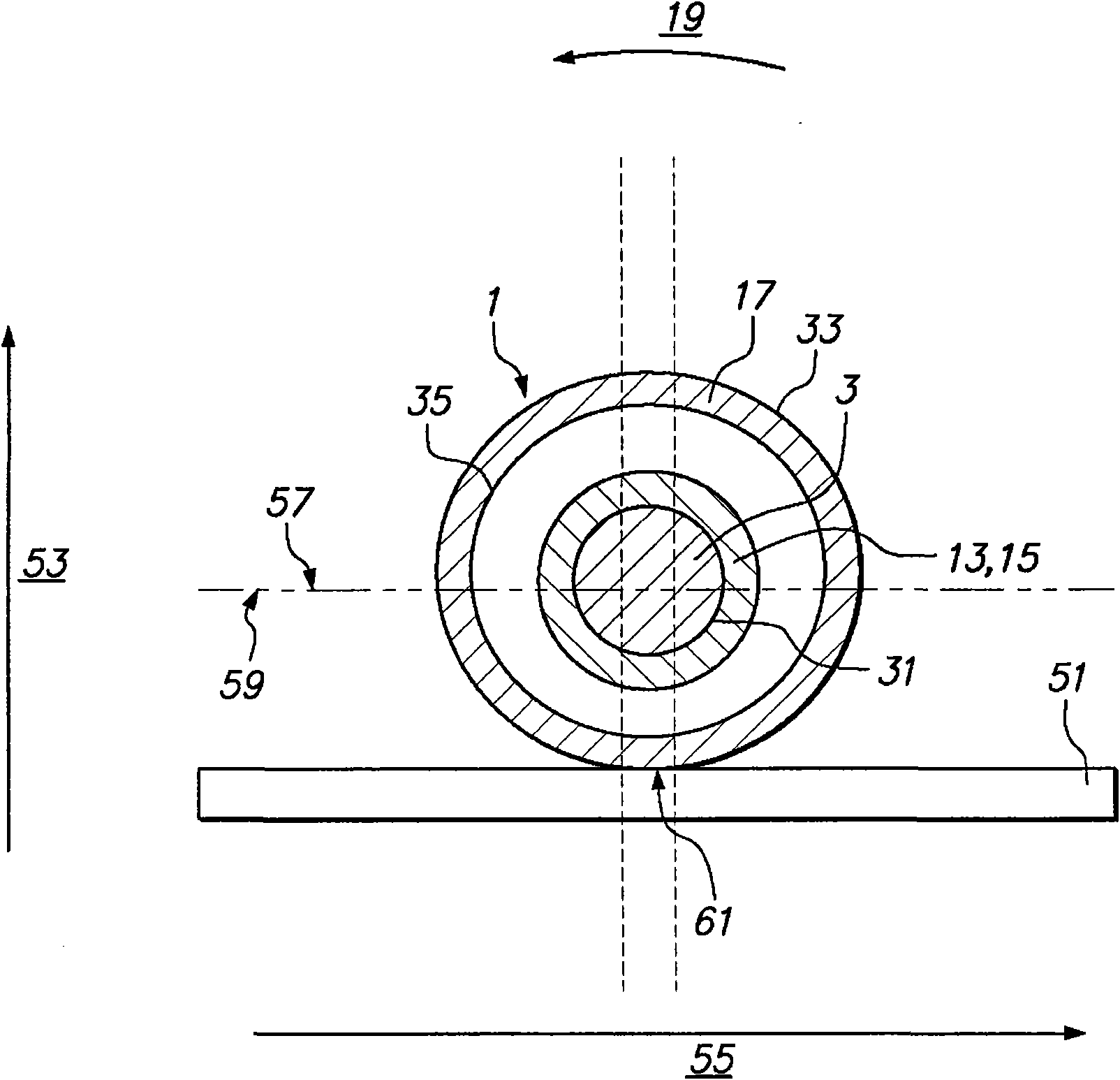
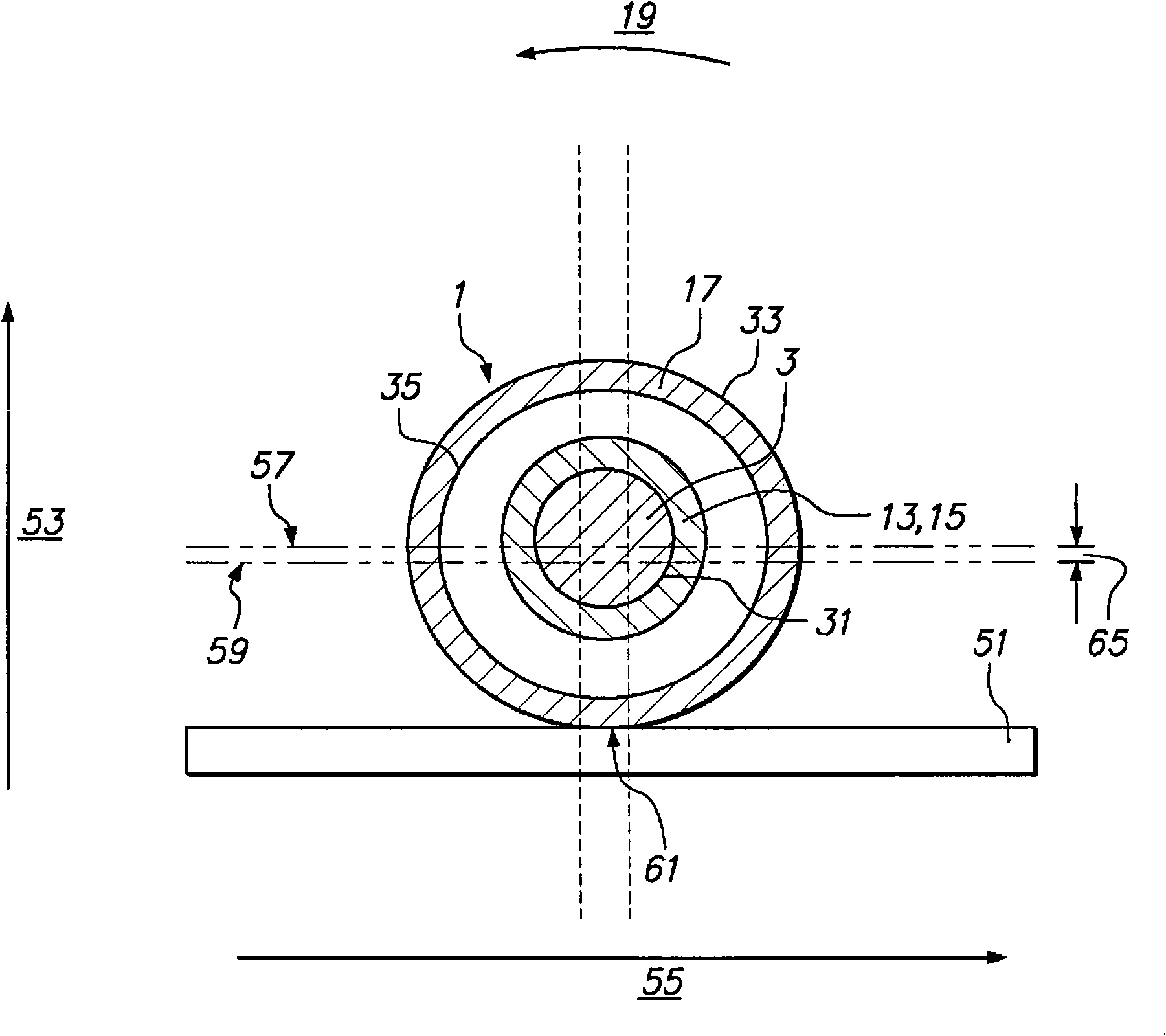
[0031] figure 1 Example transport rollers are shown. exist figure 1 In the example of , the conveying roller 1 includes a coil 5 on a main shaft 3 . The coil 5 is detachably fixed on the main shaft 3 through the first fixing element 7 and the second fixing element 9 . exist figure 1 In the example of , the spacing between adjacent windings in the flexible central portion 17 is uniform. In other embodiments, non-uniform spacing may be used.

[0032] In one embodiment, the coil 5 may include a first tapered portion 13 , a second ta...


PUM

PropertyMeasurementUnit
thicknessaaaaaaaaaa

Abstract

A transport roller for transporting articles comprises a spindle (3) and a coil (5) on the spindle (3). The coil (5) comprises a flexible central section (17), and a first end section (13) and a second end section (15) that are affixed at two opposite sides of the flexible central section (17) to the spindle (3).

Description

technical field [0001] The present invention relates to conveying mechanisms, and in particular, to rollers for conveying articles. Background technique [0002] The in-line process has been widely used in industry, for example in the production of solar cells. In these processes, objects are continuously moved along a relatively linear path to different tanks or stations where they are subjected to various treatments, including wet chemical treatments. As an example, items such as substrates or wafers can be chemically processed by alkaline solutions (eg, NaOH) and acidic solutions (eg, HF) in different wet tanks of an in-line process. Substrates or wafers can be etched, cleaned, dried or plated in different tanks or stations of the process. [0003] During transport in wet storage tanks, substrates or wafers may bob up and down or move side to side, away from the direction of transport. This movement may occur due to turbulence induced by chemical reactions, or due to i...

Claims


Application Information

Patent Timeline
Patent Type & Authority Applications(China)
IPC IPC(8): B65G39/06B65G39/04B65G39/02
CPCB65G39/06B65G39/02C25D7/0621C25D7/0657C25D17/005B65G39/04
Inventor 季静佳陈丽萍钱洪强施正荣
Owner WUXI SUNTECH POWER CO LTD
Why Eureka
Try Eureka