Dual clutch

A dual clutch, clutch housing technology, applied in clutches, friction clutches, fluid-driven clutches, etc., can solve problems such as large structural space

Inactive Publication Date: 2014-12-03
SCHAEFFLER TECH AG & CO KG
View PDF8 Cites 0 Cited by
  • Summary
  • Abstract
  • Description
  • Claims
  • Application Information

AI Technical Summary

Problems solved by technology

This results in a large installation space required for the operating system including the operating device, especially due to the large axial span of the operating device

Method used


Image

  • Dual clutch
  • Dual clutch
  • Dual clutch

Examples


Embodiment Construction

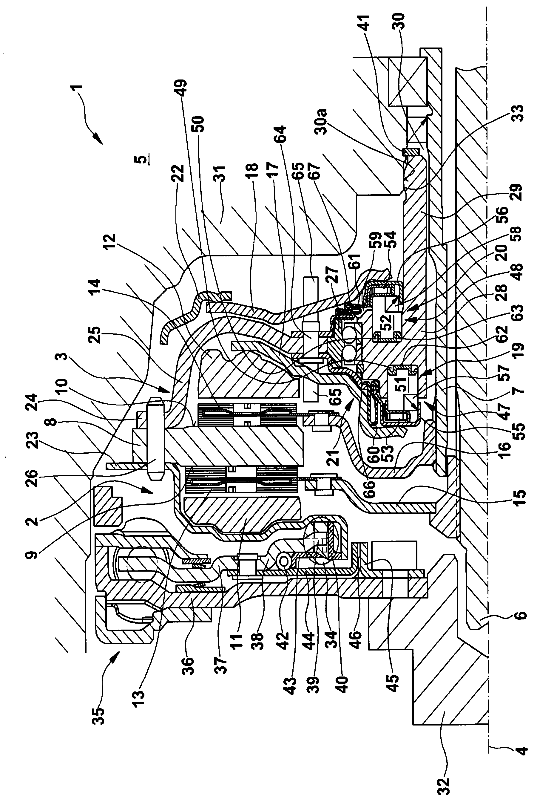
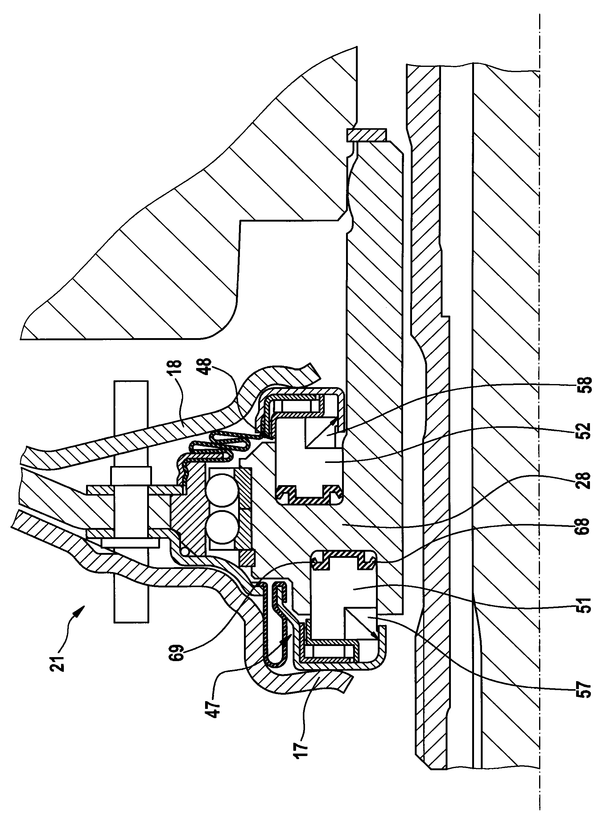
[0049] figure 1 A dual clutch 1 with friction clutches 2 , 3 arranged around a rotational axis 4 of transmission input shafts 6 , 7 of a transmission 5 is shown. The friction clutches 2, 3 are composed of a central pressure plate 8 and pressure plates 11, 12 each movable relative to a friction surface 9, 10, wherein between the friction surfaces 9, 10 and the pressure plates 11, 12 facing these friction surfaces Friction plates 13 , 14 of clutch disks 15 , 16 are arranged between the friction surfaces, and the clutch disks are each non-rotatably connected to a transmission input shaft 6 , 7 , eg toothed. In the illustrated embodiment, the pressure plates 11, 12 are acted upon by the transmission elements 17, 18, which are radially inwardly actuated by the actuating devices 19, 20 of the operating system 21 directly and without the leverage of the transmission elements 17, 18. Towards the movement, so that on the pressure plate 11, 12 by means of the transmission part 17, 18 ...


PUM


Abstract

A dual clutch which has two friction clutches, a central pressure-exerting plate and two pressure plates which are axially movable relative to the pressure-exerting plate with the interposition of the friction linings of two clutch disks, which each mesh with one gearbox input shaft, of actuating devices. The dual clutch is held at the drive-input side, with the dual clutch being supported at the gearbox side by an actuating system, which holds the two actuating devices, for actuating the pressure plates, and with the actuating system being rotatably held on the clutch housing.

Description

technical field [0001] The invention relates to a double clutch with two friction clutches driven by a drive unit, which are provided with a common clutch housing, a pressure plate with two pressure surfaces fixedly connected to the housing, and two respective Axially movable pressure plate towards a pressure bearing surface. Background technique [0002] Double clutches are known which have two friction clutches with a clutch housing and a central pressure plate fixedly connected to the housing. The pressure plate is moved by the actuating device in that radially inwardly a disk spring or a lever element is axially loaded with a predetermined clutch travel. In this case, it depends on whether the friction clutch belongs to the configuration of forced compression or forced opening, that is, forced closing or pressurization, or forced pulling, that is, forced opening. The lever is supported on the clutch housing and constitutes a lever ratio, so that the axial stroke of the...

Claims


Application Information

Patent Timeline
Patent Type & Authority Patents(China)
IPC IPC(8): F16D21/06F16D25/08F16D25/10
CPCF16D21/06F16D13/70F16D25/083F16D25/10F16D2013/706F16D2021/0669
Inventor O·诺尔I·阿格纳N·拉丁格
Owner SCHAEFFLER TECH AG & CO KG
Why Eureka
Try Eureka