Cooling device for welding device

A cooling device, welding equipment technology, applied in the direction of welding equipment, auxiliary welding equipment, welding/cutting auxiliary equipment, etc., can solve the problem of operator inconvenience

Inactive Publication Date: 2011-06-29
ESAB AB
View PDF8 Cites 13 Cited by
  • Summary
  • Abstract
  • Description
  • Claims
  • Application Information

AI Technical Summary

Problems solved by technology

This can be inconvenient for the operator

Method used


Image

  • Cooling device for welding device
  • Cooling device for welding device
  • Cooling device for welding device

Examples


Embodiment Construction

[0021] In the following description of preferred embodiments of the present invention, similar components in different figures will be denoted by the same reference numerals. The drawings are only schematic and are intended to illustrate the invention.

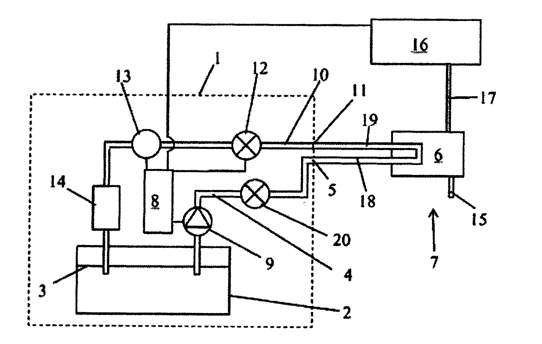
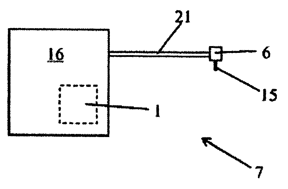
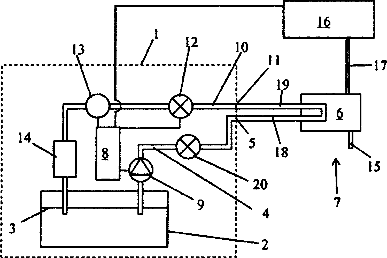
[0022] figure 1 A cooling device 1 according to an embodiment of the invention is schematically shown. Said cooling device 1 is connected to a part in the form of a welding head 6 of a welding device 7 for arc welding, so that the welding head 6 will be liquid cooled. The welding head 6 is arranged for feeding welding wire 15 to the welding area. The welding device comprises a voltage source 16 connected to the welding head by an electrical cable 17 and arranged to supply current to the welding wire 15 . The cooling device 1 comprises a coolant tank 2 containing a coolant having a coolant level 3 . The cooling device 1 also includes a liquid outlet pipe 4 with an outlet 5 for delivering the coolant from the coolant tank 2 ...


PUM


Abstract

The present invention describes a cooling device (1) used for at least one member (6) of a liquid cooling welding device (7) and a welding device with such a cooling device. The cooling device (1 ) comprises a coolant tank (2), an outlet pipe (4) for coolant from the coolant tank (2) to the member (6), which outlet pipe (4) comprises an outlet (5) for connection to the welding device (7), a return pipe (10) for returning heated liquid from the member (6) back to the coolant tank (2), which return pipe (10) comprises an inlet (11 ) for connection to the welding device (7), and a pump (9) which is connected to the outlet pipe (4) for pumping coolant from coolant tank (2) to the member (6). The cooling device (1) comprises means for preventing flow through at least one of the outlet pipe (4) and the return pipe (10) when the pump is shut off.

Description

technical field [0001] The invention relates to a cooling device for liquid cooling of equipment, especially for MIG (metal wire inert gas arc welding) / MAG (metal wire mixed gas arc welding) or TIG (tungsten welding inert gas arc welding) Welding torch or horn. The invention also relates to a welding device with such a cooling device. Background technique [0002] In MIG / MAG and TIG welding, water cooling of the welding torch and some of its components (mainly connections, clamps, flow pipes and welding head) is required. The cooling device for providing cooling water may be a separate device or part of the welding apparatus and / or a feeding device for feeding the welding wire to the welding zone. The cooling unit consists of a water tank, an outlet pipe for passing cooling water from the water tank to e.g. electrode holders, a return pipe for heated water to return from the electrode holders to the water tank, and a drain connection for pumping water from the water tank t...

Claims


Application Information

Patent Timeline
Patent Type & Authority Applications(China)
IPC IPC(8): B23K9/32B23K37/00B23K9/28
CPCB23K9/285B23K9/32B23K37/003
Inventor M·弗林克P·约翰逊
Owner ESAB AB
Why Eureka
Try Eureka