High-voltage charged display locking device

A high-voltage charged display and locking device technology, which is applied in the direction of circuit devices, battery circuit devices, emergency protection circuit devices, etc., can solve the problems of ineffective detection, breakdown of high-voltage capacitive sensors, poor safety performance, etc., and achieve accurate detection Improve performance and anti-interference performance, avoid grounding, and improve the effect of reliability

Inactive Publication Date: 2011-09-14
CHANGZHOU YINGNENG ELECTRICAL
View PDF5 Cites 5 Cited by
  • Summary
  • Abstract
  • Description
  • Claims
  • Application Information

AI Technical Summary

Problems solved by technology

[0003] There are many kinds of high-voltage live display locking devices at present, but there are two main types: the first method is a contact high-voltage capacitive sensor, but because the contact high-voltage capacitive sensor is directly connected to the high-voltage bus, when the product manufacturing quality and service performance deteriorate When there are problems such as overvoltage and overvoltage, it is easy to cause the high-voltage capacitive sensor to be broken down, causing a safety accident, so the safety performance is poor; the second is a non-contact capacitive induction high-voltage live display locking device, which is not broken down by high voltage danger, but the detection signal is easily affected by the weather and the way of power grid routing. If the lines of different voltage levels are arranged in high and low levels, they will affect each other, and effective detection will not be possible.

Method used


Image

  • High-voltage charged display locking device
  • High-voltage charged display locking device
  • High-voltage charged display locking device

Examples


Embodiment Construction

[0014] The present invention will be further described in detail below in conjunction with the accompanying drawings and specific embodiments.

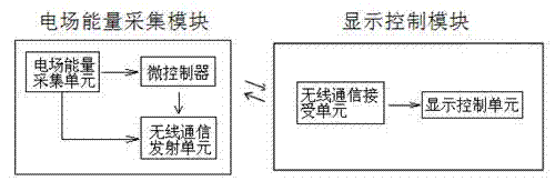
[0015] Embodiment, take the display locking device used for the detection of the live state of the high-voltage line as an example, such as figure 1 As shown, the high-voltage live display locking device involved in the present invention includes an insulating protection box, an electric field energy collection module and a display control module. The electric field energy collection module is built in the insulation protection box, and it includes an electric field energy collection unit, a microcontroller and a wireless communication transmitting unit, the display control module includes a display control unit and a wireless communication receiving unit. Among them, the output end of the electric field energy collection unit is respectively connected with the power supply end of the microcontroller and the transmitting unit, so as t...


PUM


Abstract

The invention relates to a high-voltage charged display locking device which comprises an electric filed energy acquisition module and a display control module, wherein the display control module comprises a display control unit and a wireless communication receiving unit; the electric field energy acquisition module comprises an electric field energy acquisition unit, a microcontroller and a wireless communication transmitting unit; the output end of the electric filed energy acquisition unit is connected with the power supply end of the microcontroller; the signal output end of the microcontroller is connected with the input end of the wireless communication transmitting unit; the electric field energy acquisition unit comprises an electric field energy acquisition wire, a rectifying circuit, a filter circuit, an energy storing circuit and a voltage-stabilizing circuit which are electrically connected in sequence; and one of two ends of the electric field energy acquisition wire, serving as the two input ends of the rectifying circuit, is suspended, and the other end of the electric field energy acquisition wire is connected to the surface of high-voltage equipment. The locking device has the advantages of safety in use, reliability in detection, capability of realizing normal work of the electric field energy acquisition module without a special power supply and high using value.

Description

technical field [0001] The invention relates to a high-voltage live display locking device, in particular to a display locking device for indicating the electrification status of high-voltage power transmission and transformation equipment and lines. Background technique [0002] In the power system, the high-voltage live display locking device is an important safety device for detecting, indicating and blocking whether the high-voltage equipment and lines have high-voltage electricity, so as to prevent the electrified grounding switch from being accidentally connected or the grounding wire, or with a grounding knife Gate, grounding wire wrong power transmission, to ensure the safety of personnel and equipment. [0003] There are many kinds of high-voltage live display locking devices at present, but there are two main types: the first method is a contact high-voltage capacitive sensor, but because the contact high-voltage capacitive sensor is directly connected to the high-...

Claims


Application Information

Patent Timeline
Patent Type & Authority Applications(China)
IPC IPC(8): H02J7/02H02H9/04G01R19/155
Inventor 庄孟文丁威苍后亮
Owner CHANGZHOU YINGNENG ELECTRICAL
Why Eureka
Try Eureka