Noise cancellation device and noise cancellation program

A noise and noise technology, applied in the field of noise removal program, can solve the problems of reduced noise removal ability, smaller time difference, poor interference sound power, etc., and achieve the effect of improving noise removal ability

Inactive Publication Date: 2011-10-26
MITSUBISHI ELECTRIC CORP
View PDF1 Cites 16 Cited by
  • Summary
  • Abstract
  • Description
  • Claims
  • Application Information

AI Technical Summary

Problems solved by technology

[0005] In the method described in Patent Document 1, there is a problem that the output signals of the microphones are directly compared with each other, so the power difference or time difference between the target sound and the interference sound varies depending on the characteristics, installation directions, and installation intervals of the installed microphones. Small and reduced noise removal capability

Method used


Image

  • Noise cancellation device and noise cancellation program
  • Noise cancellation device and noise cancellation program
  • Noise cancellation device and noise cancellation program

Examples


Embodiment approach 1

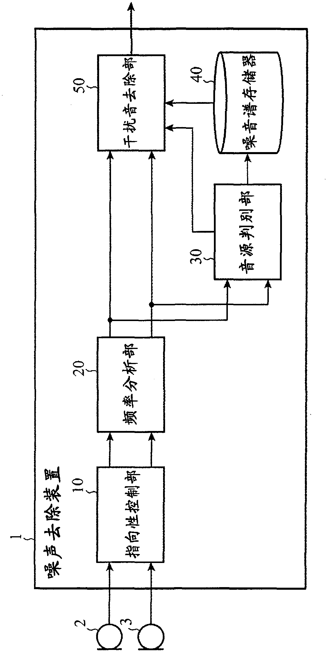
[0027] figure 1 It is a block diagram showing the configuration of the noise removal device 1 according to Embodiment 1 of the present invention. In the figure, a noise removal device 1 is a device that calculates a noise-removed signal from output signals of a plurality of microphones 2, 3, and includes a directivity control unit 10, a frequency analysis unit 20, a sound source discrimination unit 30, a noise spectrum memory 40, Interfering sound removal unit 50 . In addition, in Embodiment 1, the microphones 2 and 3 are used as an example of a plurality of microphones, but any number may be used.

[0028] The directivity control unit 10 controls the directivity of the output signals of the plurality of microphones 2 and 3 through signal processing, and outputs a main beam signal whose directivity is directed in the direction of the target sound and a sub-beam whose dead angle is directed in the direction of the target sound. Signal.

[0029] The frequency analysis section...

Embodiment approach 2

[0090] The noise removal device 1 according to Embodiment 1 above assumes a situation where the direction of the target sound is fixed in one direction. Therefore, noise cannot be removed accurately when the direction of the target sound changes, for example, when the position of the speaker changes. Embodiment 2 aims to solve such a problem.

[0091] Figure 7 It is a block diagram showing the configuration of the noise removal device 1 according to Embodiment 2 of the present invention. exist Figure 7 in, with figure 1 In contrast, the new element is the point where the target sound direction notification unit 60 and the filter coefficient memory 70 are set, and the figure 1 The same or corresponding parts are attached with the same symbols and descriptions thereof are omitted.

[0092] The target sound direction notifying unit 60 is a means for discriminating and notifying the target sound direction based on external input (not shown) such as a sensor, and outputs the...

Embodiment approach 3

[0098] The noise removal device 1 according to Embodiments 1 and 2 described above does not consider the use after noise removal. However, when the noise removal device 1 is used as preprocessing for speech recognition, for example, depending on the language, the frequency characteristics are processed nonlinearly by noise removal, which may cause a mismatch with the acoustic model and degrade the recognition performance. influences. Embodiment 3 aims to solve such a problem.

[0099] Figure 9 It is a block diagram showing the configuration of the noise removal device 1 according to Embodiment 3 of the present invention. exist Figure 9 in, with figure 1 Compared with, the new element is the point that the language notification part 80 is set, and the figure 1 The same or corresponding parts are attached with the same symbols and descriptions thereof are omitted.

[0100] The language notification unit 80 acquires the language used from a device connected downstream of ...


PUM


Abstract

A directivity control section (10) calculates a main beam signal the directivity of which is directed toward the direction of an object sound and a side beam signal the blind spot of which is directed toward the direction of the object sound from the output signals of a plurality of microphones (2, 3) by signal processing, which a frequency analyzing section (20) converts into spectrums. A sound source discriminating section (30) discriminates whether the sound source is a sound, a stationary noise, or a non-stationary noise from the spectrums of the main beam signal and the side beam signal to output the result of the discrimination of the sound source and calculates the average spectrum which is the statistic of a noise with respect to the main beam signal. A disturbance sound cancellation section (50) subtracts the average spectrum from the spectrum of the main beam signal to cancel the disturbance sound.

Description

technical field [0001] The present invention relates to a noise removal device and a noise removal program for removing noise using a plurality of microphones. Background technique [0002] Conventionally, in voice recognition and hands-free calling, there has been a problem that recognition performance and clarity are degraded due to superimposition of noise on voice. As a technique for solving such a problem, various noise removal methods have been proposed, and as one method, there is a noise removal method using a plurality of microphones. Generally, by using a plurality of microphones, the noise suppression effect can be improved compared to the case of using one microphone. [0003] As a noise removal method using a plurality of microphones, a method of comparing input power differences and time differences of a plurality of microphones to remove components other than target sounds is known (for example, refer to Patent Document 1). In this method, by performing freq...

Claims


Application Information

Patent Timeline
Patent Type & Authority Applications(China)
IPC IPC(8): G10L15/20G10L21/02H04R1/40H04R3/00G10L21/0208G10L21/0216G10L21/0232
CPCG10L21/0208G10L2021/02166H04R3/005
Inventor 成田知宏
Owner MITSUBISHI ELECTRIC CORP
Why Eureka
Try Eureka