Failure detection system and failure detection method

a failure detection system and failure detection technology, applied in the direction of electrical equipment, etc., can solve the problems of affecting the difference result of audio signals, the accuracy of forming directivity deteriorates, and the size of the microphone array device increases, so as to suppress the deterioration of the accuracy of forming directivity of voices in the predetermined direction

Active Publication Date: 2016-02-04
PANASONIC INTELLECTUAL PROPERTY MANAGEMENT CO LTD
View PDF11 Cites 134 Cited by
  • Summary
  • Abstract
  • Description
  • Claims
  • Application Information

AI Technical Summary

Benefits of technology

[0011]An object of the present disclosure is to provide a failure detection system and a failure detection method in which, even during actual using, characteristics of each microphone element included in a microphone array device are mo...

Problems solved by technology

Therefore, the number of arrayed microphone elements increases, which results in the increase of the size of a microphone array device.
In the adaptive microphone array device in which the delay difference method is used, in a case where characteristics deteriorate or a failure occurs in any of the microphone elements, it influences the difference result of the audio signal.
Then, the audio signal in which the surrounding noises are suppressed in the target direction cannot be obtained, and thus, the accuracy of forming the directivity deteriorates.
However, when it is desired to form directivity in an arbitrary direction using a microphone a...

Method used


Image

  • Failure detection system and failure detection method
  • Failure detection system and failure detection method
  • Failure detection system and failure detection method

Examples


first embodiment

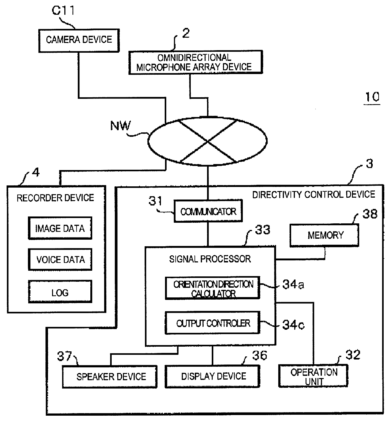
[0043]FIG. 1 is a block diagram illustrating a system configuration of failure detection system 10 in the first embodiment. Failure detection system 10 illustrated in FIG. 1 is configured to include omnidirectional microphone array device 2, camera device C11, directivity control device 3, and recorder device 4. Omnidirectional microphone array device 2 collects a voice in the sound collection region in which failure detection system 10 is installed, that is, for example, collects a voice generated from a person as an example of a sound source existing in the sound collection region.

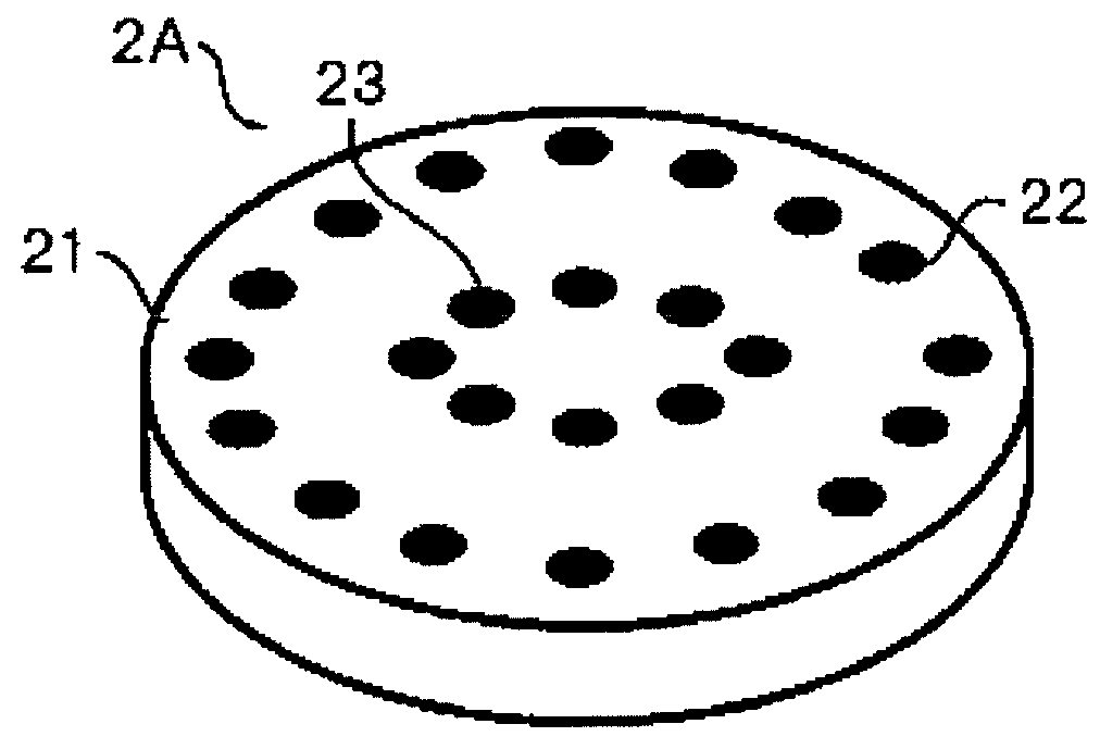
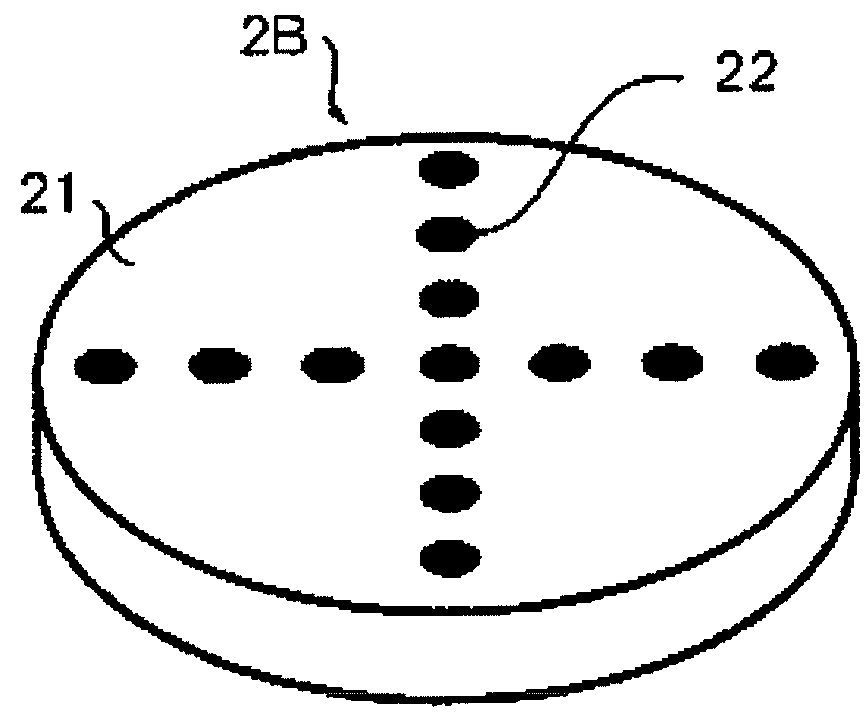
[0044]A housing of omnidirectional microphone array device 2 is described as having a disk shape as an example in the present embodiment. However, the shape is not limited to the disk shape, and for example, the shape may be a donut shape or a ring shape (refer to FIG. 2A to FIG. 2E).

[0045]In omnidirectional microphone array device 2, for example, a plurality of microphone units 22 and 23 is concentrical...

second embodiment

[0160]In the first embodiment, omnidirectional microphone array device 2 transmits the error notification packet or the error recovery packet in addition to the voice data packet. In the second embodiment, an example will be described, in which omnidirectional microphone array device 2G transmits packet PKT of the voice data (voice data packet) while adding microphone failure data on header HD of packet PKT. In addition, in the second embodiment, in contrast to the first embodiment, directivity control device 3 does not perform the processing of detecting the failure of each individual microphone element.

[0161]In addition, the configuration of the failure detection system in the second embodiment is the same as that in the first embodiment. Therefore, since the same reference signs are given to the same configuration elements as those in the first embodiment, the description thereof will not be repeated.

[0162]FIG. 15A is a block diagram illustrating an internal configuration of omni...

third embodiment

[0168]In the first embodiment, omnidirectional microphone array device 2 performs the failure detection of microphone element 22i. In the third embodiment, an example will be described, in which the omnidirectional microphone array device 2 only transmits the packet of the voice data and does not perform the processing of detecting the failure of the microphone element, and directivity control device 3 performs the processing of detecting the failure of the microphone element.

[0169]The failure detection system in the third embodiment has almost the same configuration as in first embodiment. Therefore, the same reference signs will be given to the configuration elements same as those in the first embodiment, and the descriptions thereof will not be repeated.

[0170]FIG. 17 is a flowchart illustrating an operation procedure of a directivity forming operation and an error detection processing performed by directivity control device 3 in the third embodiment. In description of FIG. 17, th...


PUM


Abstract

A failure detection system includes an omnidirectional microphone array device having a plurality of microphone elements and a directivity control device that calculates a delay time of a voice propagated from a sound source to each microphone element and forms a directivity of the voice using the delay time and the voice collected by the omnidirectional microphone array device, and detects a failure of the microphone element. A smoothing unit calculates an average power of one microphone element. An average calculator calculates a total average power of a plurality of usable microphone elements included in the omnidirectional microphone array device. A comparison unit compares whether or not a difference between the average power and the total average power exceeds a range of ±6 dB, and determines whether the microphone element is in failure based on the comparison result.

Description

BACKGROUND[0001]1. Technical Field[0002]The present disclosure relates to a failure detection system and failure detection method configured to detect a failure in a sound collection element.[0003]2. Description of the Related Art[0004]When collecting a sound of interest such as a voice, a sound collection technology with a high SN ratio is strongly desired so as not to collect an unnecessary sound such as a noise, an interference sound, or the like. In order to achieve such a technology, it is considered that signal processing using a sound collection device (microphone array device) configured of a plurality microphone elements is effective.[0005]As an example of the signal processing using the microphone array device, there is a method (delay-sum method) in which the directivity of a voice is formed in a predetermined direction by adding a different delay time for each microphone element to the audio signal collected by each microphone element, and then summing the audio signals....

Claims


Application Information

Patent Timeline
IPC IPC(8): H04R29/00
CPCH04R29/004
Inventor MATSUMOTO, HIROYUKIWATANABE, SHUICHITOKUDA, TOSHIMICHITSUJI, HISASHIIZUMI, AKITOSHIYOSHIKUNI, SHINTARO
Owner PANASONIC INTELLECTUAL PROPERTY MANAGEMENT CO LTD
Why Eureka
Try Eureka