

Lens control system, lens controller, and operating apparatus
a control system and lens technology, applied in the direction of printers, instruments, cameras focusing arrangements, etc., can solve problems such as invalidating non-linear processing
- Summary
- Abstract
- Description
- Claims
- Application Information
AI Technical Summary
Benefits of technology
Problems solved by technology
Method used
Image

Examples
first embodiment
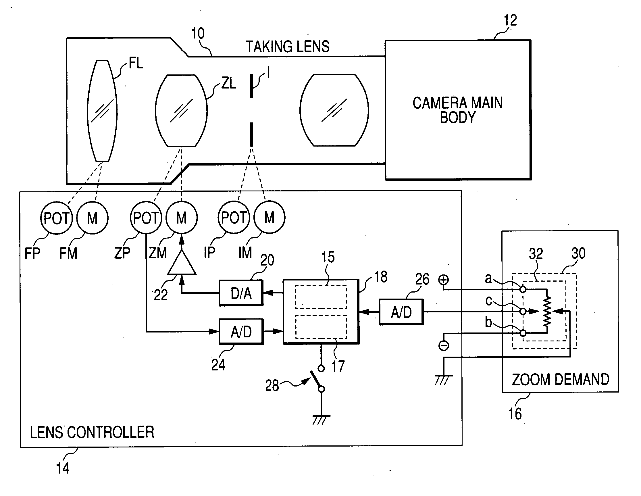
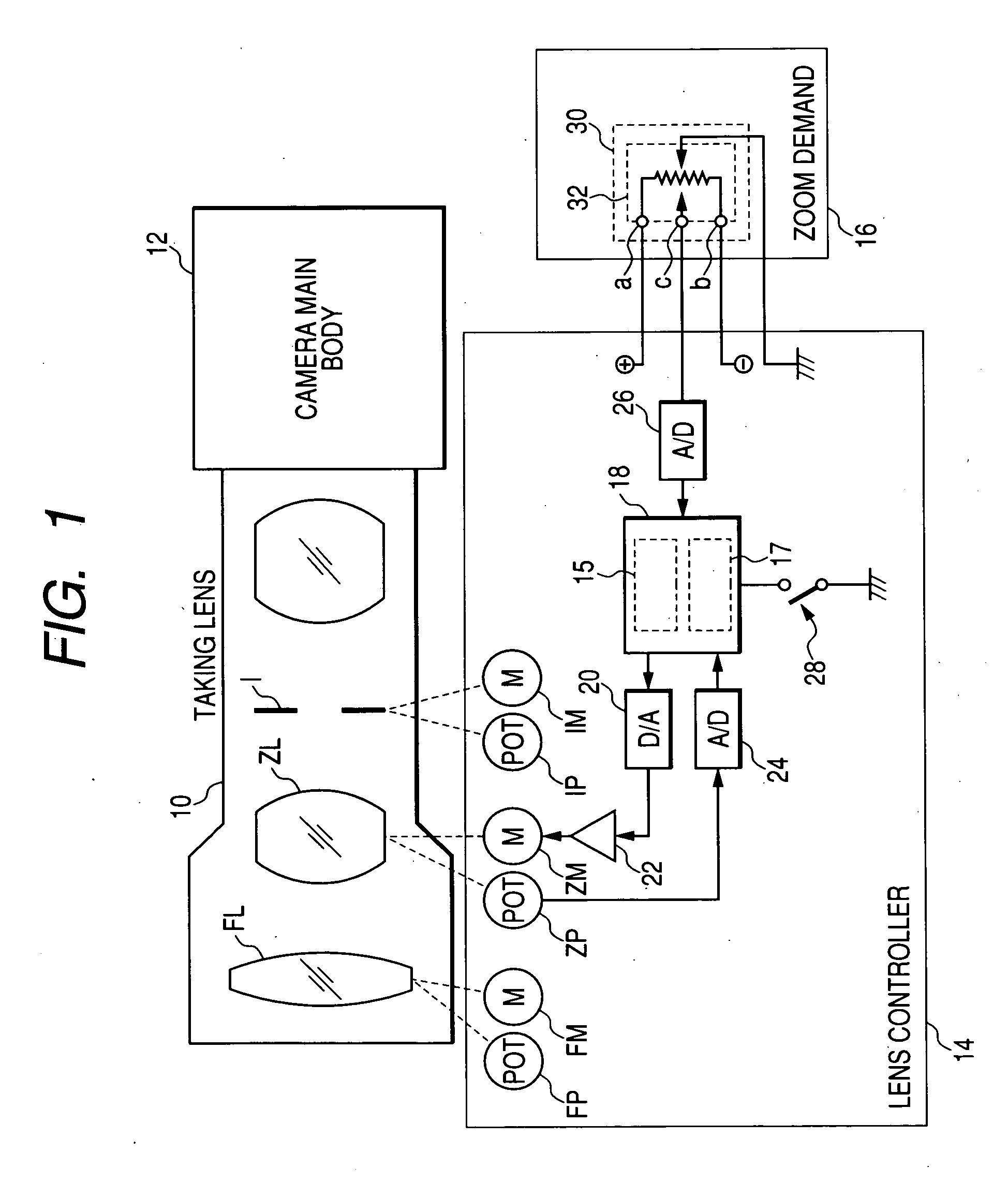
[0030]FIG. 1 is a block diagram showing a first embodiment having a configuration pertaining to zoom control operation of a lens control system to which the present invention is applied. As illustrated, the lens control system comprises a taking lens 10 secured on a camera main body 12 of a broadcast television camera by means of a mount; a lens controller 14 for controlling the taking lens 10; and as an a zoom demand 16 connected to the lens controller 14 by means of a cable or the like.
[0031] For instance, in addition to various types of fixed lenses, a focus lens (group) FL for controlling focus, a zoom lens (group) ZL for controlling a zooming factor (a focal distance), and an iris I for controlling the quantity of light are provided in the taking lens 10 as movable optical components.
[0032] The lens controller 14 corresponds to, e.g., a drive unit to be attached to a lens barrel of the taking lens 10 in the case of a lens apparatus called an ENG lens. In the case of a lens app...
second embodiment
[0053] Next, a second embodiment in which the non-linear processing to be performed by the CPU 18 (the non-linear processing portion) of the lens controller 14 is appropriately switched between valid and invalid will be described by reference to a block diagram shown in FIG. 7. Individual constituent sections shown in FIG. 7 which are identical with or analogous in operation to those shown in FIG. 1 are assigned the same reference numerals as those shown in FIG. 1, and their repeated explanations are omitted. In FIG. 7, an identification signal output section 60 which outputs an identification signal indicating whether the characteristic of the signal is non-linear or linear (i.e., an identification signal indicating whether an output control signal is non-linear or linear) to the zoom demand 16 is provided in lieu of the non-linear processing activation / deactivation switch 28 shown in FIG. 1. The identification signal output section 60 outputs, to the CPU 18, a high-level identific...
third embodiment
[0059] Next, a in which the non-linear processing to be performed by the CPU 18 of the lens controller 14 can be switched between valid and invalid—is shown in the block diagram of FIG. 9. Individual constituent sections shown in FIG. 9 which are identical with or analogous in operation to those shown in FIG. 4 are assigned the same reference numerals as those shown in FIG. 4, and their repeated explanations are omitted. FIG. 9 shows a case where the pan head system 50 is connected as an operating apparatus to the lens controller 14. In place of the non-linear processing activation / deactivation switch 28 shown in FIG. 4, the pan head system 50 is provided with an identification signal output section 80 for outputting an identification signal indicating whether zooming position control or speed control is to be performed (i.e., whether the control signal output from the zoom demand 16 indicates a target speed control or target position of the zoom lens). The identification signal out...
PUM
 Abstract
Description
Claims
Application Information