ground flare
A ground torch and chimney technology, applied in the direction of combustion type, lighting and heating equipment, burner noise control, etc., can solve the problem of high cost and achieve the effect of preventing resonance/vibration
- Summary
- Abstract
- Description
- Claims
- Application Information
AI Technical Summary
Problems solved by technology
Method used
Image

Examples
Embodiment approach 1
[0089]
[0090] In the embodiment described below, the natural frequency of the low-frequency sound generated by the ground flare tower body is shifted to the high-frequency side to prevent resonance with the natural frequency of combustion in the combustion chamber.
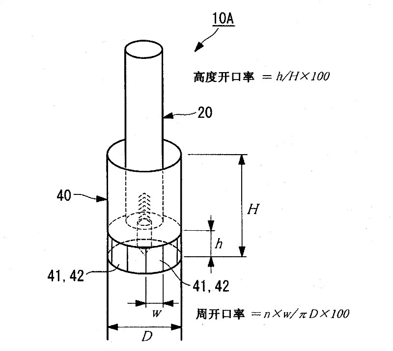
[0091] in such as image 3 In the shown ground flare 10A, a damper opening 41 is partially provided in the damper 40 , and the damper opening 41 is closed with a non-walled plate 42 to change the natural frequency. That is, after a part of the damper 40 is cut to form the damper opening 41 , the damper opening 41 is attached to the damper opening 41 to close it. The non-wall surface material 42 used here not only blocks the wind and prevents leakage of audible sound, but also prevents flames from being seen from the outside through the windshield opening 41, as long as it is a material that does not function as a wall for low-frequency sounds.
[0092] The windshield opening 41 that removes a part of the wind...
Embodiment approach 2
[0121]
[0122] In the embodiment described below, the natural frequency of the low-frequency sound generated by the ground flare tower body is shifted to the bass side to prevent resonance with the natural frequency of combustion in the combustion chamber. That is, if Figure 12A ~ Figure 15 As shown, the frequency of occurrence is reduced and the sound pressure level of low-frequency noise is reduced by extending the windshield portion.
[0123] In this way, use Figure 15 And the combustion chamber position ζ' of the combustion chamber 11 obtained by [Mathematical formula 1] shown below is set to be in the range of 2.2 to 3.4 from the entrance Wi of the windshield 40A with respect to the length (total passage length) including the chimney 20 and the windshield 40A. Inside.
[0124] [mathematical formula 1]
[0125] ζ ′ = ( 1 - L 1 ...
Embodiment approach 3
[0136]
[0137] In the embodiment described below, the ground flare towers are multiplied, and a plurality of towers with different main frequencies are combined to reduce the sound pressure level.
[0138] In this embodiment, for example Figure 16 As shown, two ground flares 10a, 10b split in two are arranged in such a way as to satisfy the necessary capacity. In this case, the ground flares 10a and 10b divided into two are set so that the main frequencies are different by changing the length of the chimneys 20a and 20b, etc., and the main frequency of the ground flare 10b with a longer air column length is lower. , the main frequency of the ground flare 10a with a short air column length becomes a high pitch. That is, among the two ground flares 10a and 10b, ground flares with different primary frequencies are arranged side by side. In addition, in this division example, both the chimney and the windshield are divided into two. In addition, reference numerals 40a and 4...
PUM
 Abstract
Description
Claims
Application Information
 - R&D Engineer
- R&D Manager
- IP Professional
- Industry Leading Data Capabilities
- Powerful AI technology
- Patent DNA Extraction
Browse by: Latest US Patents, China's latest patents, Technical Efficacy Thesaurus, Application Domain, Technology Topic.
© 2024 PatSnap. All rights reserved.Legal|Privacy policy|Modern Slavery Act Transparency Statement|Sitemap