
input device

An input device and input unit technology, applied in the input/output process of data processing, instruments, electrical digital data processing, etc., can solve the problems that the operator cannot confirm the change of the display state, it is difficult to confirm the auditory feedback, and the input object is blocked.

Active Publication Date: 2011-11-30
KYOCERA CORP
View PDF2 Cites 0 Cited by
  • Summary
  • Abstract
  • Description
  • Claims
  • Application Information

AI Technical Summary

Problems solved by technology

[0007] However, this auditory feedback can be difficult to recognize in noisy environments and is not applicable when the device is in silent mode
In addition, when using such visual feedback, if the input object displayed on the display unit is small, the operator may not be able to confirm the change of the display state, especially when the operator inputs with a finger, the view of the input object is blocked by the finger

Method used


Image

  • input device
  • input device
  • input device

Examples


no. 1 example

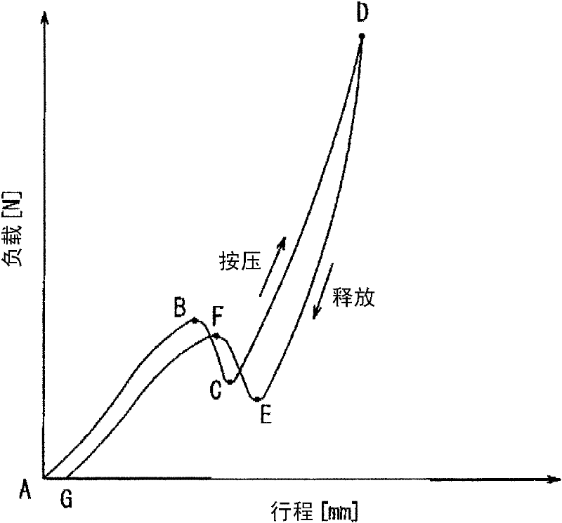
[0069] Figure 5 is a block diagram illustrating a schematic configuration of the input device according to the first embodiment of the present invention. The input device has a display panel 11, a touch panel 12, a load detection unit 13, a vibration unit 14, and a control unit 15 for controlling overall operations. The display panel 11 constitutes a display unit for displaying input objects such as input buttons, and may be, for example, a liquid crystal display panel, an organic EL display panel, or the like. The touch panel 12 constitutes an input unit for receiving a pressing input to the display panel 11, and may be of a known type such as a resistive film type or a capacitive type, or the like. The load detection unit 13 detects a pressing load on the touch panel 12, and may include, for example, a strain sensor. The vibration unit 14 vibrates the touch panel 12 and may include, for example, a piezoelectric vibrator.

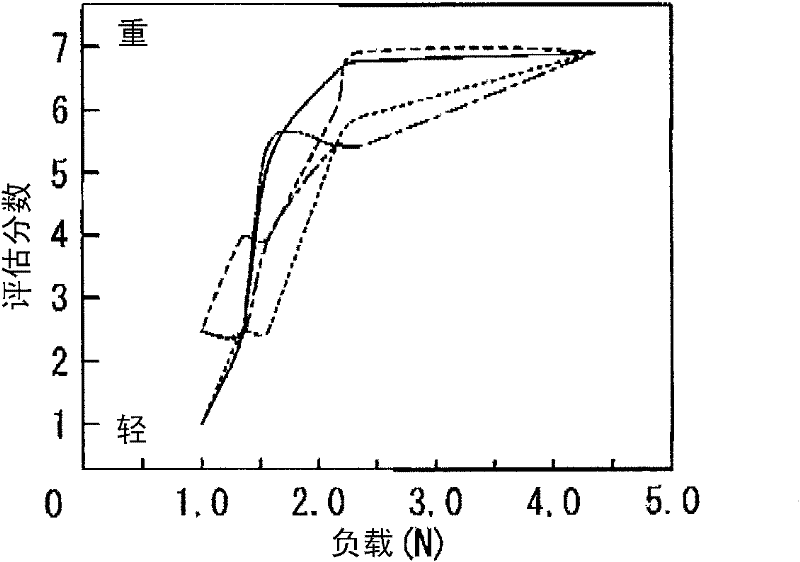
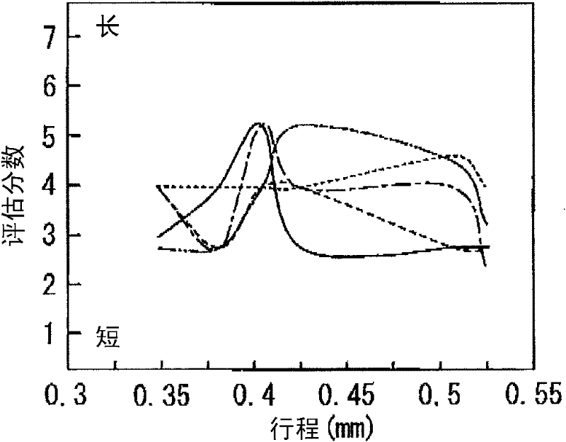
[0070] Figure 6 show Figure 5 An example hou...

no. 2 example

[0083] Figure 10 and Figure 11 An input device according to a second embodiment of the present invention is illustrated. Figure 10 is a block diagram schematically constructed, Figure 11 is its front view. The input device is mounted on, for example, a mobile terminal, such as Figure 10 As shown, the input device has a touch panel 41 as an input unit for receiving a press input, a position detection unit 42 for detecting an input position on the touch panel 41 , and a A display panel 43 to display information, a load detection unit 44 to detect a pressing load on the touch panel 41, a vibration unit 45 to vibrate the touch panel 41, and a control unit 46 to control overall operations.

[0084] Such as Figure 11 As shown, a plurality of input objects 41a, such as numeric keys, have been provided on the touch panel 41 by printing, adhesive, or the like. For each input object 41a, in order to prevent erroneous input of pressing a plurality of adjacent input objects 41...


PUM


Abstract

The invention provides an input device, which has: an input unit (12), used for receiving pressing input; a load detection unit (13), used for detecting the pressing load on the input unit (12); a vibration unit (14), used for In the vibration input unit (12); and the control unit (15), used for controlling the vibration unit (14) ) to provide a click feeling to the object pressing the input unit (12), and after receiving the input to the input unit (12), when the pressing load detected by the load detection unit (13) satisfies the ratio of receiving the input unit When the predetermined level of the input of (12) is lower than the level, the driving of the vibration unit (14) is controlled, thereby providing a click feeling to the object. Thereby, when the operator operates the push type input unit, a real click feeling similar to that obtained when operating a push-button switch is provided, which enables continuous input operation without an unfamiliar feeling.

Description

[0001] Cross References to Related Applications [0002] This application claims priority from Japanese Patent Application No. 2008-326297 filed on December 22, 2008, the entire contents of which are hereby incorporated by reference. technical field [0003] The present invention relates to an input device having an input unit for receiving a press input. Background technique [0004] In recent years, in information equipment, home electric appliances, etc., input devices (such as touch panels, touch switches, etc.) having an input unit in the form of a panel for receiving input by pressing are commonly used as devices for receiving input. An input unit for input operations by the user. There are various types of such an input unit, such as a resistive film type, a capacitive type, and the like. All of these input units are for receiving a pressing input of a finger or a stylus, and, unlike a button switch, these input units are not displaced even when pressed. [0005] T...

Claims


Application Information

Patent Timeline
Patent Type & Authority Applications(China)
IPC IPC(8): G06F3/041
CPCG06F3/0414G06F3/016G06F3/0416G06F2203/04105G06F3/04142
Inventor 青野智刚盐川雄太田代郁
Owner KYOCERA CORP
Learn More