Dust collection device for vacuum drier

A vacuum dryer and dust removal device technology, applied in the direction of filtration and separation, fixed filter elements, chemical instruments and methods, etc., can solve the problems of shortening the service life of vacuum pumps, troublesome production operations, etc., achieve long cleaning intervals, and reduce labor Strength, the effect of protecting the vacuum pump

Active Publication Date: 2013-07-24
JIANGYIN CHEM MASCH CO LTD
View PDF3 Cites 0 Cited by
  • Summary
  • Abstract
  • Description
  • Claims
  • Application Information

AI Technical Summary

Problems solved by technology

[0002] In the current production of chemical fiber industry, the dust removal device of the vacuum dryer includes a dust removal barrel and a vacuum pump. The dust removal barrel includes a barrel body, an air inlet pipe, an orifice plate and pebbles. There is a square hole on the side wall of the barrel body for putting pebbles. , there is a vacuum port on the top of the barrel, a sewage outlet on the bottom of the barrel, the air intake pipe is inserted into the whole body, the orifice plate is placed flat in the middle of the barrel, and pebbles are laid on the orifice plate; the vacuum pump and the vacuum hole of the dust removal barrel Connected; the dust and water generated during the drying of the vacuum dryer go through the dust removal barrel of the dust removal device of the vacuum dryer and the vacuum pump, and the dust and water enter and fall into the dust removal barrel, and the water and dust deposit at the bottom of the dust removal barrel to form dust sludge ; Every ten days or so, it is necessary to open the sewage valve to slowly drain the accumulated water, and then open the sewage outlet to clean up the dust and mud inside, which will bring great trouble to the production operation, and sometimes the improper operation of the dust will enter Vacuum pumps, shortening the service life of vacuum pumps

Method used


Image

  • Dust collection device for vacuum drier
  • Dust collection device for vacuum drier

Examples


Embodiment Construction

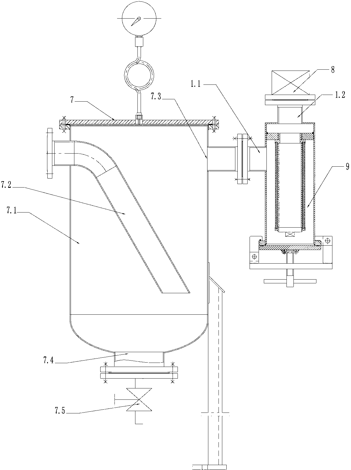
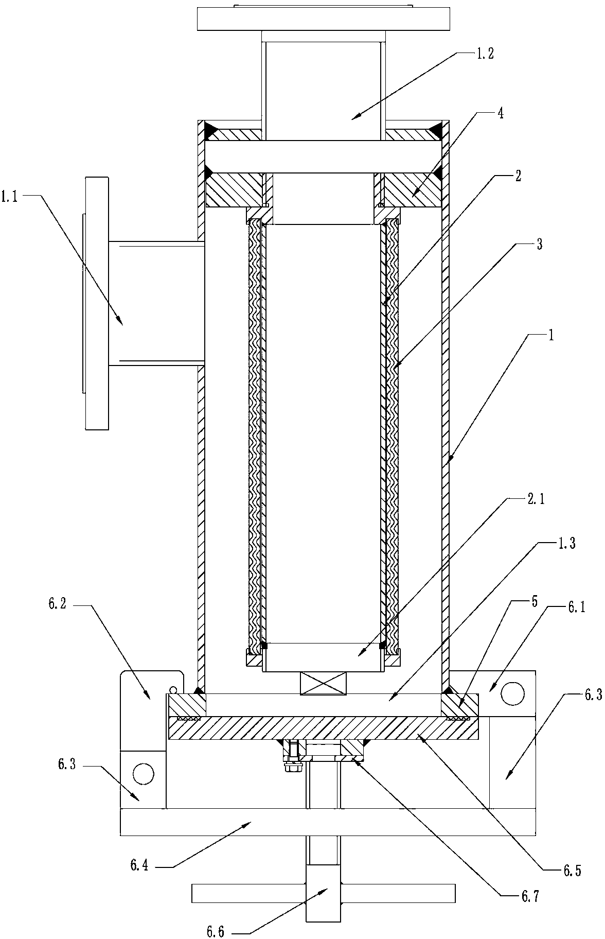
[0012] Such as figure 1 and figure 2 As shown, a dust removal device of a vacuum dryer includes a dust removal barrel 7 and a vacuum pump 8, and is characterized in that the dust removal barrel 7 includes a barrel body 7.1 and an air inlet pipe 7.2, and a vacuum hole 7.3 is provided on the side wall of the barrel body 7.1, and There is a sewage outlet 7.4 at the bottom of the body 7.1, and the air intake pipe 7.2 is inserted into the whole body 7.1; a dust remover 9 is arranged between the dust removal bucket 7 and the vacuum pump 8, and the dust remover 9 includes an outer cylinder 1, a filter tube 2, a filter screen 3, and a filter element fixed Plate 4, flange 5 and quick opening device; there are several through holes on the side wall of filter tube 2; the quick opening device includes ear plate 6.1, hook plate 6.2, connecting plate 6.3, support plate 6.4, cover plate 6.5 and screw rod 6.6, the connection plate 6.3 is respectively fixed at both ends of the support plate ...


PUM


Abstract

The invention relates to a dust collection device for a vacuum drier. The dust collection device comprises a dust collection barrel and a vacuum pump, and is characterized in that: the dust collection barrel comprises a barrel body and an air inlet pipe; a vacuumizing hole is formed on the side wall of the barrel body; a drain outlet is formed at the bottom of the barrel body; the air inlet pipe is inserted into the barrel body; a dust collector is arranged between the dust collection barrel and the vacuum pump; a dust inlet of the dust collector is connected with the vacuumizing hole of the dust collection barrel; and a vacuumizing interface of the dust collector is connected with the vacuum pump. The dust collection device has the advantages that: when the vacuum drier is used for drying, dust is separated from water completely, the dust collection device is not needed to be cleaned frequently, and the production efficiency is improved while the labor intensity of workers is reduced.

Description

technical field [0001] The invention relates to a dust removal device, in particular to a dust removal device of a vacuum dryer used in the production of chemical fiber industry. Background technique [0002] In the current production of chemical fiber industry, the dust removal device of the vacuum dryer includes a dust removal barrel and a vacuum pump. The dust removal barrel includes a barrel body, an air inlet pipe, an orifice plate and pebbles. There is a square hole on the side wall of the barrel body for putting pebbles. , there is a vacuum port on the top of the barrel, a sewage outlet on the bottom of the barrel, the air intake pipe is inserted into the whole body, the orifice plate is placed flat in the middle of the barrel, and pebbles are laid on the orifice plate; the vacuum pump and the vacuum hole of the dust removal barrel Connected; the dust and water generated during the drying of the vacuum dryer go through the dust removal barrel of the dust removal de...

Claims


Application Information

Patent Timeline
Patent Type & Authority Patents(China)
IPC IPC(8): B01D29/15
Inventor 陈少忠陆廷宏汪华
Owner JIANGYIN CHEM MASCH CO LTD
Why Eureka
Try Eureka