revolving door

A technology for revolving doors and turnstiles, applied in the field of revolving doors, can solve problems such as visual discomfort and high roof structure

Inactive Publication Date: 2011-12-21
多玛德国有限公司
View PDF12 Cites 4 Cited by
  • Summary
  • Abstract
  • Description
  • Claims
  • Application Information

AI Technical Summary

Problems solved by technology

Therefore, most of the time, the revolving door drive is installed above the turnstiles, resulting in a visually uncomfortable, high roof structure

Method used


Image

  • revolving door
  • revolving door
  • revolving door

Examples


Embodiment Construction

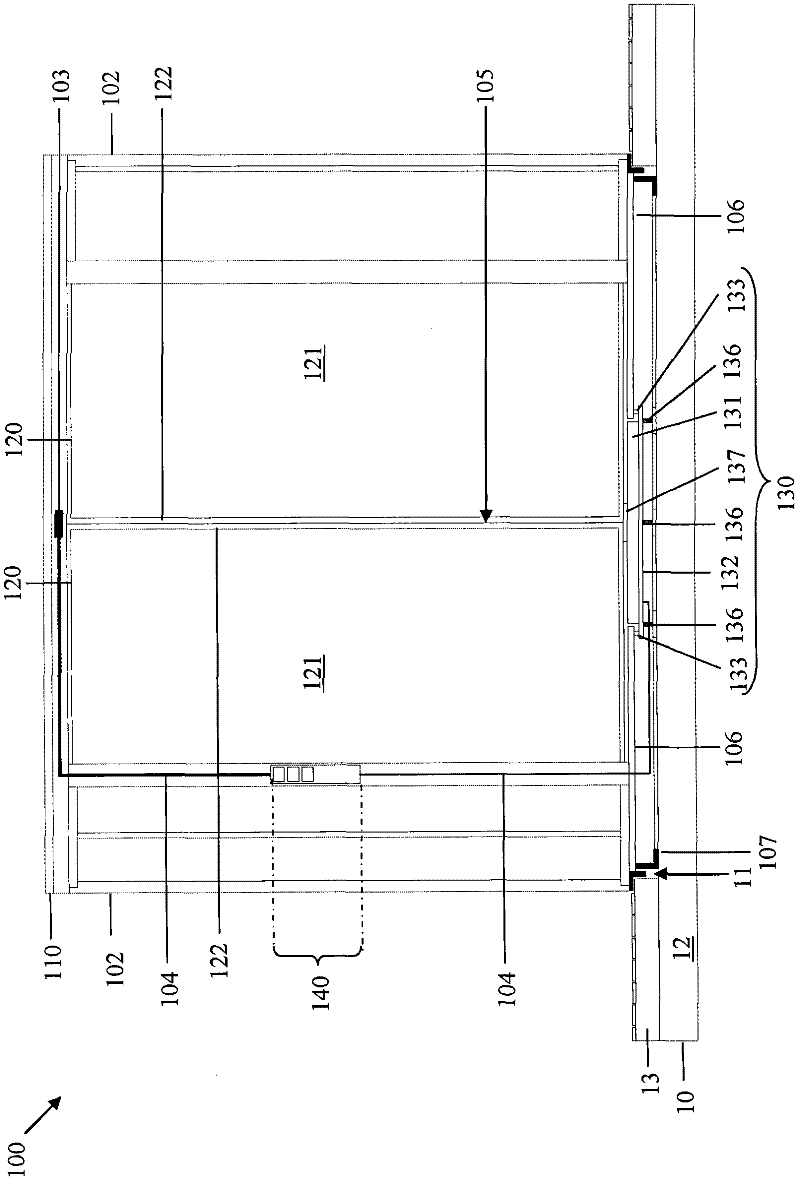
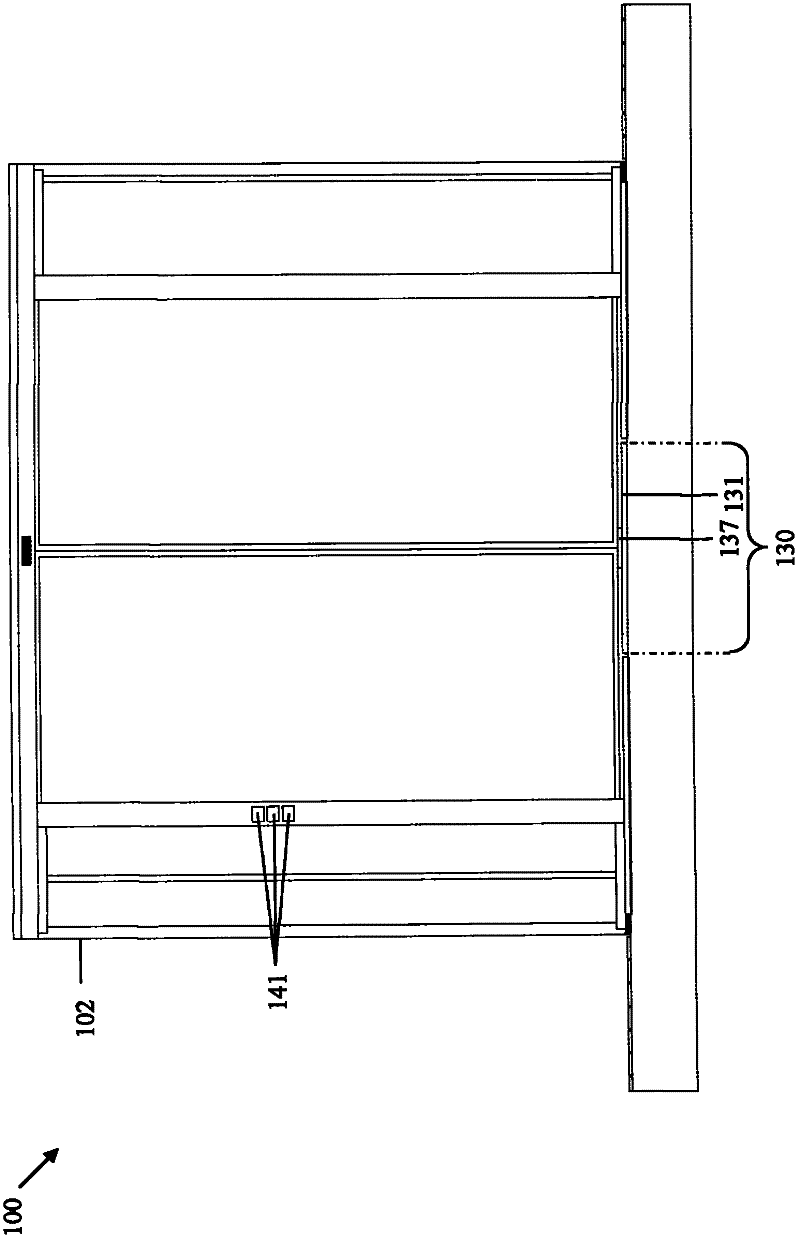
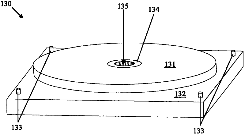
[0017] figure 1 A revolving door 100 according to a first embodiment of the invention is shown. The revolving door 100 is conceived as a free standing. This means that the revolving door is installed as a separate component in a building which is not shown. The revolving door 100 comprises a turnstile formed by means of a revolving column 105 to which a number of revolving door leaves 120 are attached in a known manner. By way of example, the revolving door leaves 120 are designed as glass door leaves, which each comprise a frame profile 122 into which the respective glass pane 121 is inserted. The swivel column 105 is arranged on a drive device 130 together with the fixedly attached revolving door leaf 120 and is adapted to rotate freely in the revolving door 100 . The driving device 130 is buried in the ground 10 of the building.

[0018] Basically, the floor 10 comprises an undecorated floor 12 and a covering layer 13 in which the receiving space for the drive device 13...


PUM


Abstract

The invention provides a revolving door (100) having a driving device (130) operatively connected to a turnstile (105, 120) of the revolving door (100) and driving the turnstile. The door swings. The drive device (130) includes a drive motor configured as a multi-pole electric motor, the axis of rotation of which extends parallel or coaxially with the axis of rotation of the turnstiles (105, 120) and which has an angle equal to or smaller than 80mm height.

Description

technical field [0001] The present invention relates to automatic revolving doors, ie revolving doors provided with a drive motor. Background technique [0002] From document EP 2 072 737 A2 a revolving door system is known which has a motor drive in its roof structure above the turnstile. The turnstile is formed by means of a swivel column to which a revolving door leaf is attached. A motor drive is operatively connected to the rotary column via an output shaft and a reversing mechanism. The output shaft extends substantially perpendicularly with respect to the longitudinal extension of the swivel column. [0003] Since the drive device requires an enormous torque for turning the turnstiles of such doors, the dimensions of the drive motor are relatively large, which results in the need for a bulky space above or below the turnstile. Therefore, most of the time, the revolving door drive is installed above the turnstiles, resulting in a visually uncomfortable, high roof st...

Claims


Application Information

Patent Timeline
Patent Type & Authority Applications(China)
IPC IPC(8): E05F15/12E06B3/90
CPCE05F15/106E05Y2900/10E05Y2600/10E05Y2600/452E05Y2800/264E05F15/608
Inventor 斯文·布施迈克尔·格兰茨托马斯·施米茨
Owner 多玛德国有限公司
Why Eureka
Try Eureka