Liquid crystal display device

A technology of a liquid crystal display device and a liquid crystal layer, which is applied to static indicators, nonlinear optics, instruments, etc., can solve problems such as poor gamma characteristics and large offsets, and achieve improved gamma characteristics, better display effects, and improved display quality effects

Active Publication Date: 2014-07-09
TCL CHINA STAR OPTOELECTRONICS TECH CO LTD
View PDF4 Cites 0 Cited by
  • Summary
  • Abstract
  • Description
  • Claims
  • Application Information

AI Technical Summary

Problems solved by technology

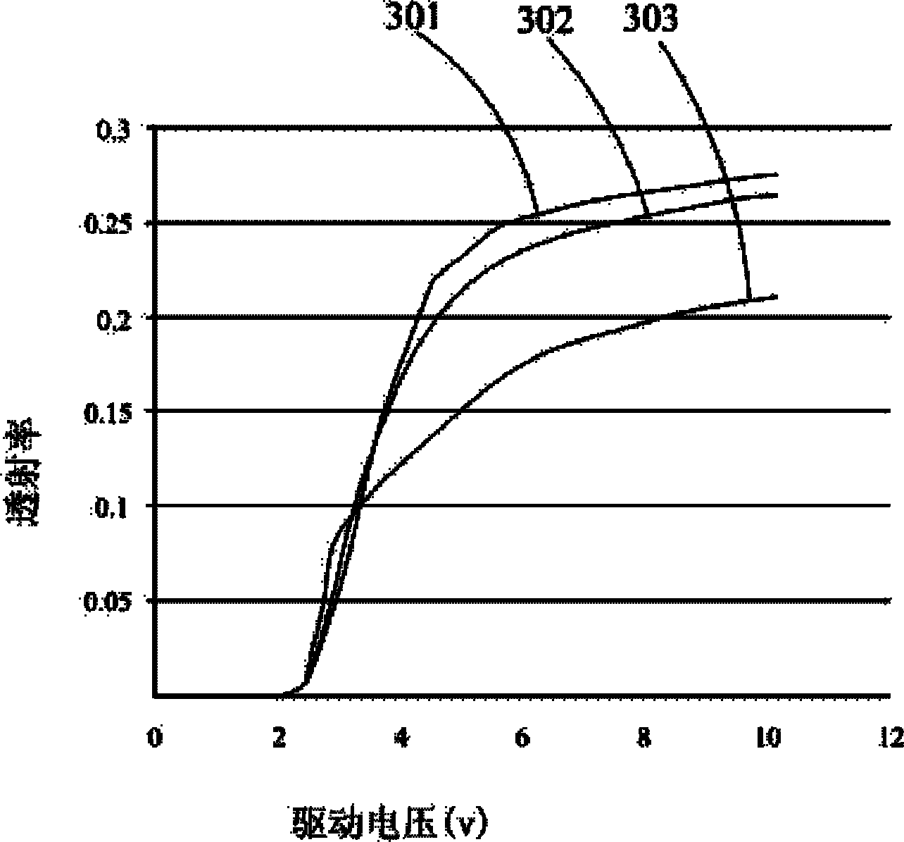
Since the offset between the curve 502 and the curve 503 and the gray level characteristic curve 501 of the normal viewing angle is relatively large, it can be seen that the gamma characteristic effect of the existing liquid crystal display device 1 is poor

Method used


Image

  • Liquid crystal display device
  • Liquid crystal display device
  • Liquid crystal display device

Examples


Embodiment Construction

[0038] See Image 6 , Image 6 It is a structural schematic diagram of a preferred embodiment of the liquid crystal display device of the present invention. like Image 6 As shown, the liquid crystal display device 50 of the present invention includes a liquid crystal display panel 51 and a backlight module 52 .

[0039] In this embodiment, the liquid crystal display panel 51 and the backlight module 52 are stacked. Wherein, the liquid crystal display panel 51 is used to provide display images, and the backlight module 52 provides the required backlight for the liquid crystal display panel 51 .

[0040] Figure 7 show Image 6 A schematic structural diagram of a pixel unit in the middle liquid crystal display panel 51 . like Figure 7 As shown, the liquid crystal display panel 51 of the present invention includes a plurality of pixel units 60 arranged in a matrix, wherein each pixel unit 60 further includes a first sub-pixel electrode 61 and a second sub-pixel electrode...


PUM


Abstract

Provided is a liquid crystal display device (50), including: a plurality of pixel units (60) arranged in a matrix pattern, each of the pixel units (60) further including a first sub-pixel electrode (61) and a second sub-pixel electrode (62), wherein the first sub-pixel electrode (61) is provided in the center of the pixel unit (60) and the second sub-pixel electrode (62) is provided around the first sub-pixel electrode (61). By way of the above method, the liquid crystal display device (50) can improve the ? viewing angle features, achieve better display effects, and improve the display quality.

Description

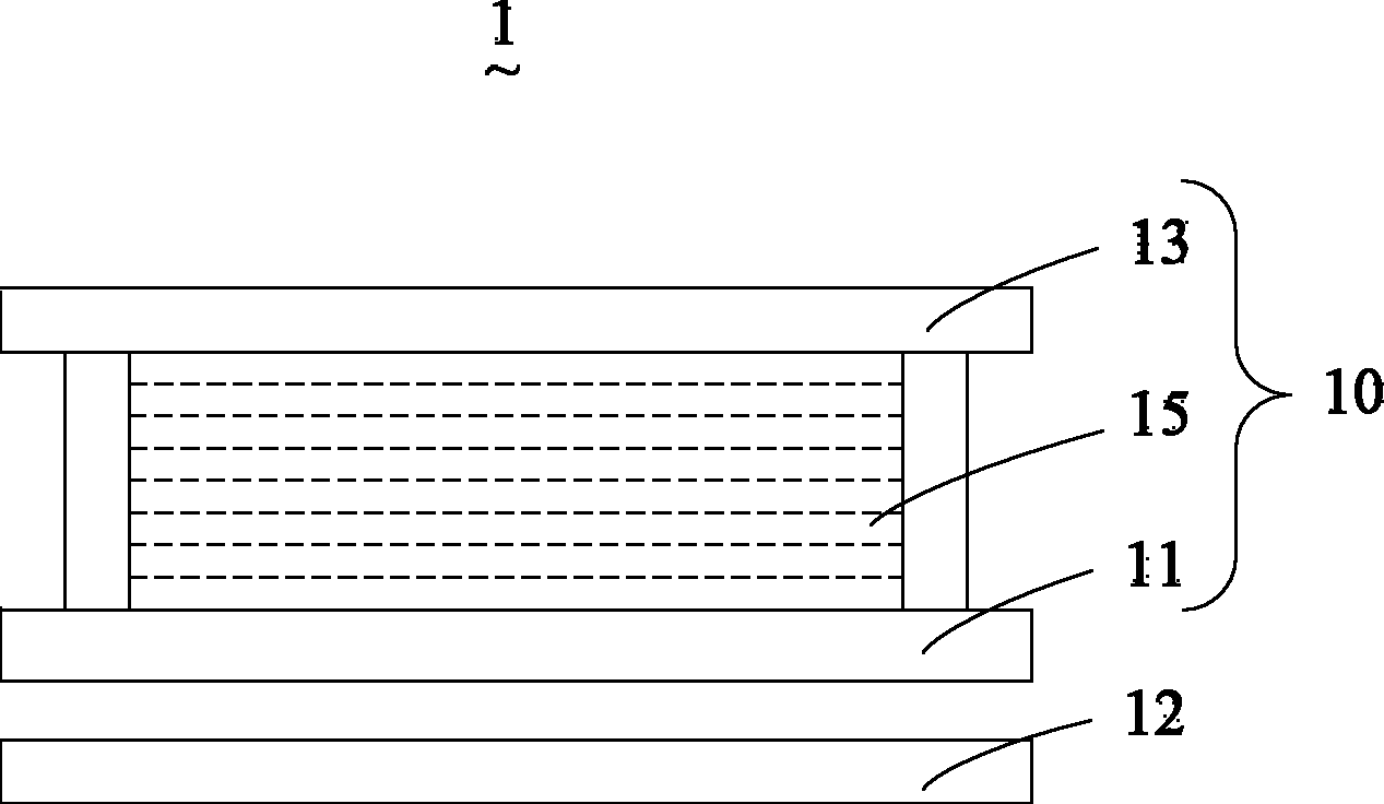
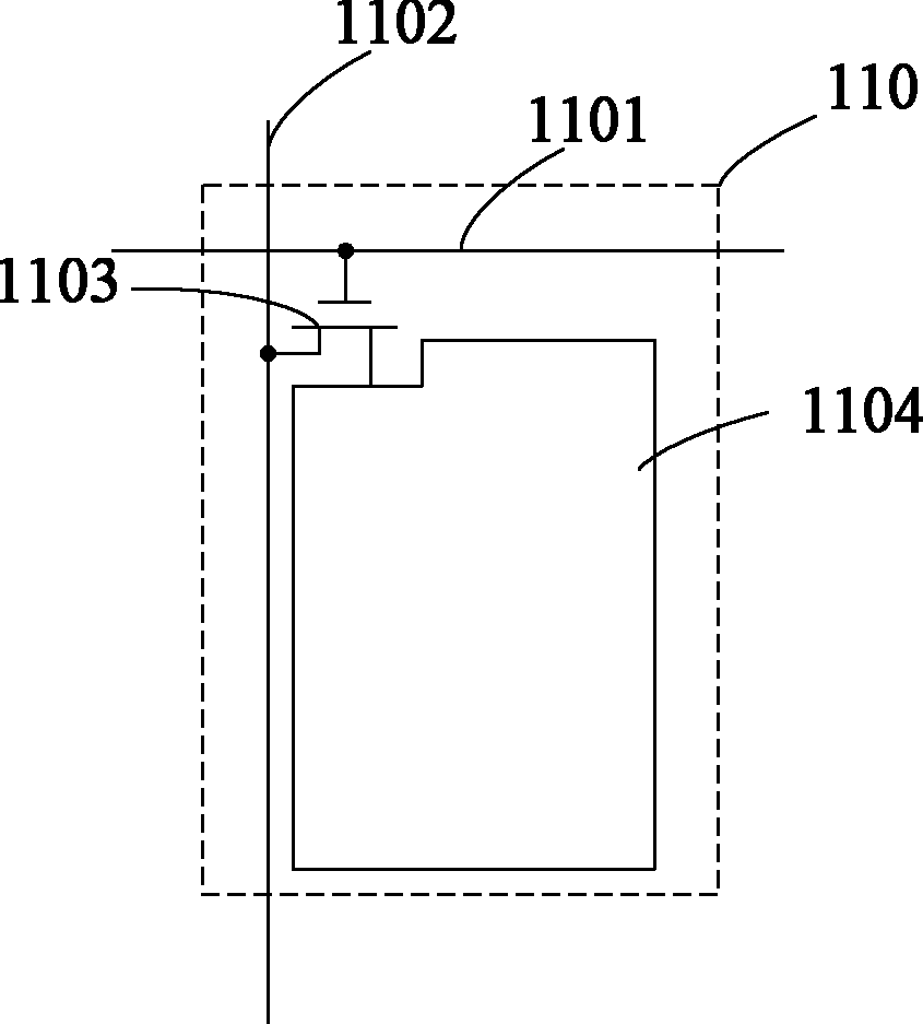
technical field [0001] The invention relates to the technical field of liquid crystal display, in particular to a liquid crystal display device capable of improving gamma characteristics. Background technique [0002] In recent years, liquid crystal display technology has developed rapidly and has become a hot research topic. Because liquid crystal display devices have the advantages of high resolution, thin thickness, light weight and low energy consumption, they are widely used in medical, advertising, military, exhibition, entertainment and other display fields. figure 1 It is a structural schematic diagram of an existing liquid crystal display device. The conventional liquid crystal display device 1 includes a liquid crystal display panel 10 and a backlight module 12 . Wherein, the liquid crystal display panel 10 includes a first substrate 11 , a second substrate 13 and a liquid crystal layer 15 . The first substrate 11 is an electrode substrate, the second substrate ...

Claims


Application Information

Patent Timeline
Patent Type & Authority Patents(China)
IPC IPC(8): G02F1/1362G02F1/1368G02F1/133G02F1/1343
CPCG02F1/1393G02F1/134309G02F2001/134345G02F1/133753G02F1/13624G02F1/134345
Inventor 李仕琦姚晓慧廖作敏
Owner TCL CHINA STAR OPTOELECTRONICS TECH CO LTD
Why Eureka
Try Eureka