
Multi-view image coding device, multi-view image decoding method, multi-view image decoding device, multi-view image decoding method

A multi-viewpoint image and coding method technology, applied in multi-viewpoint image coding devices and multi-viewpoint image decoding devices and fields, can solve problems such as coding efficiency degradation, and achieve the effects of reducing prediction difference and reducing code amount

Active Publication Date: 2014-07-09
NIPPON TELEGRAPH & TELEPHONE CORP +1
View PDF12 Cites 0 Cited by
  • Summary
  • Abstract
  • Description
  • Claims
  • Application Information

AI Technical Summary

Problems solved by technology

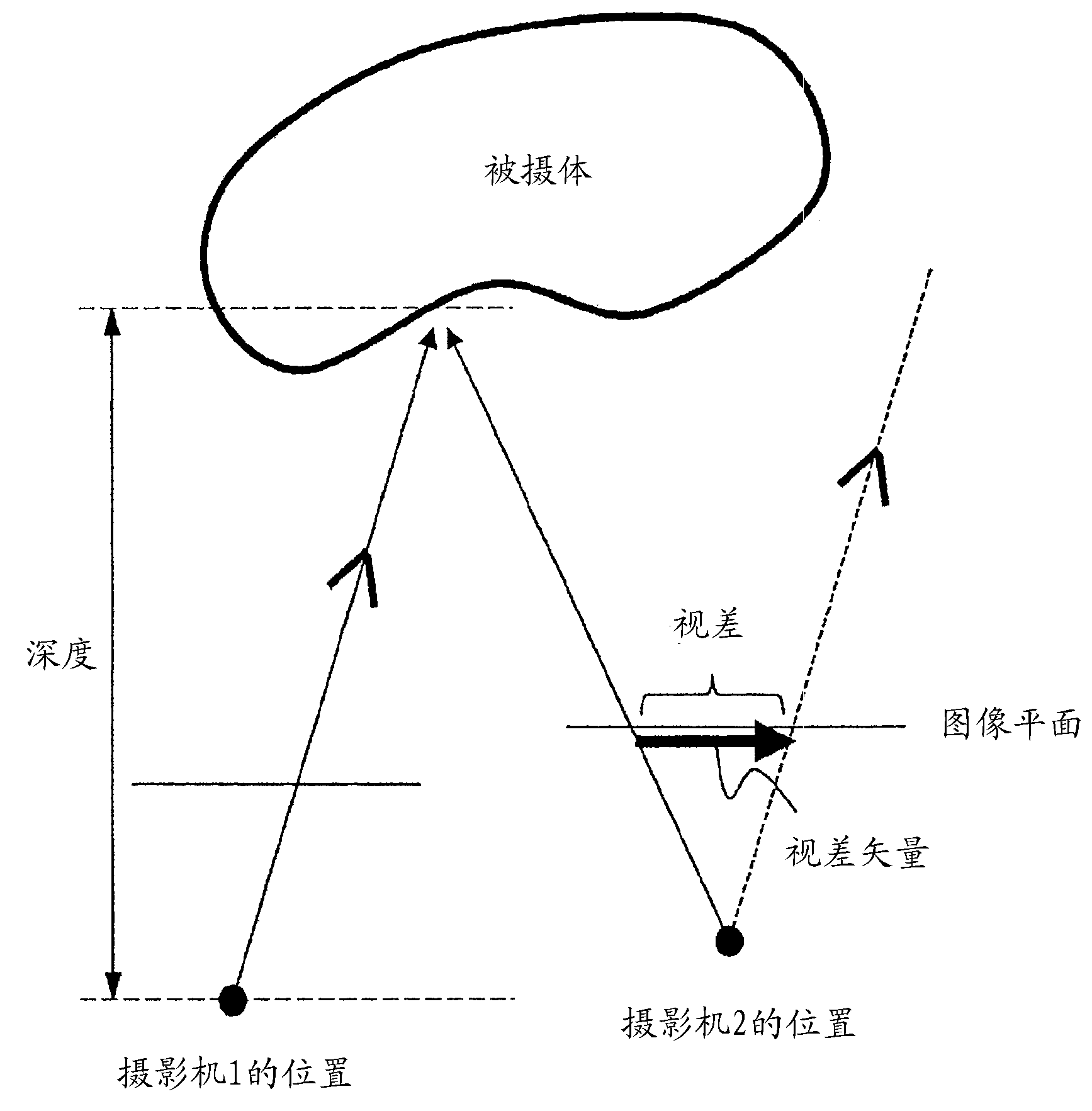
[0009] In the prediction using the image taken by the other camera, when there is individual difference in the response of the imaging element of the camera, or when gain control and gamma correction are performed for each camera, or the depth of field and aperture of each camera Coding efficiency degrades when different settings such as , or when there are direction-dependent lighting effects in the scene

Method used


Image

  • Multi-view image coding device, multi-view image decoding method, multi-view image decoding device, multi-view image decoding method
  • Multi-view image coding device, multi-view image decoding method, multi-view image decoding device, multi-view image decoding method
  • Multi-view image coding device, multi-view image decoding method, multi-view image decoding device, multi-view image decoding method

Examples


Embodiment Construction

[0059] Hereinafter, the present invention will be described in detail with reference to the drawings showing embodiments of the present invention.

[0060] In addition, in the following description, by adding information to the video (frame) and depth information that can specify the position (the information sandwiched by the mark [] is a coordinate value or an index that can be associated with the coordinate value. ), so as to indicate the image signal and depth information (defined for each image) of the subject photographed in the pixel at that position.

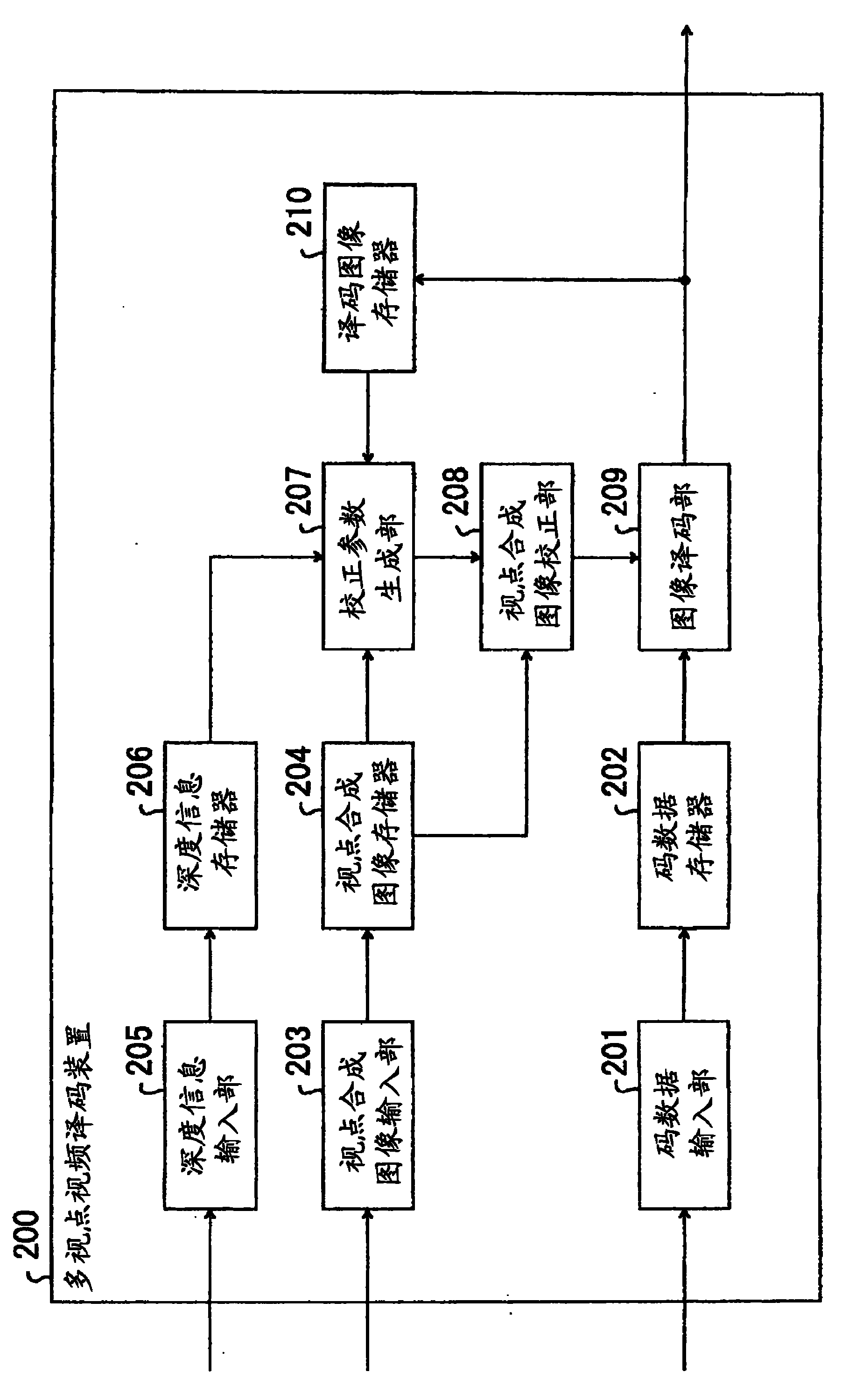
[0061] [1] Multi-viewpoint video encoding device according to the first embodiment of the present invention

[0062] figure 1 The device configuration of the multi-view video encoding device 100 according to the first embodiment of the present invention is shown.

[0063] Such as figure 1 As shown, in the multi-viewpoint video encoding device 100 of the present embodiment, the encoding target image input unit 101 inputs the im...


PUM


Abstract

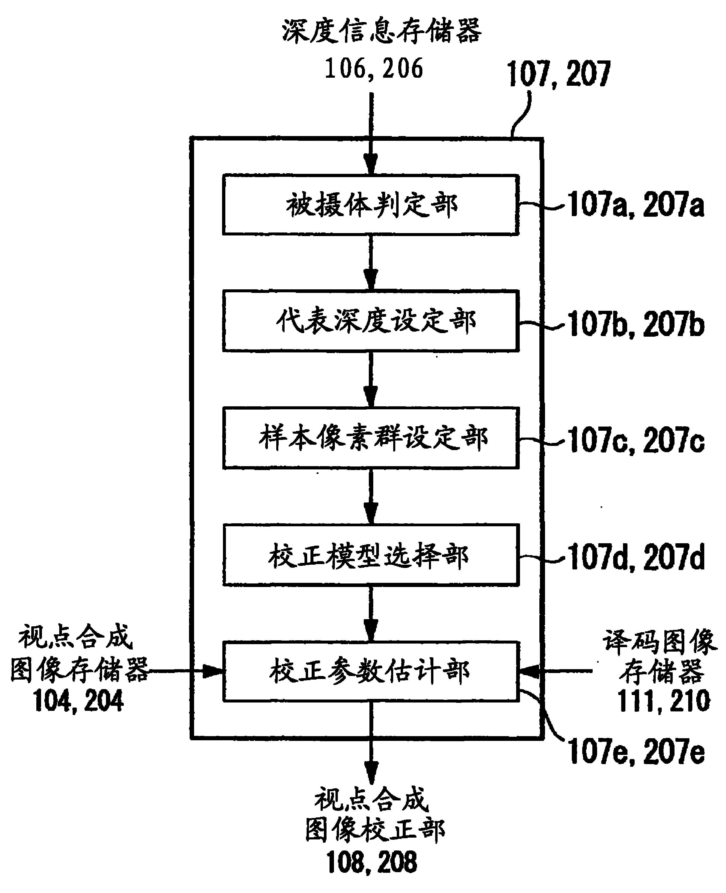
The multi-viewpoint image coding / decoding device of the present invention first obtains depth information of a subject photographed in a processing target area. Next, in an already coded (decoded) area adjacent to the processing target area, a pixel group of the same subject as that of the coding target area is obtained based on the depth information, and a sample pixel group is set. Next, a view synthesis image is generated for the pixels included in the sample pixel group and the pixels included in the processing target area. Next, parameters for correcting brightness and color mismatch are estimated from the view synthesis image and the decoded image in the sample pixel group. Next, using the estimated correction parameters, the view synthesis image generated for the processing target area is corrected to generate a predicted image.

Description

Technical field [0001] The present invention relates to a multi-viewpoint image encoding method and device for encoding an image captured by a certain subject by multiple cameras, and a multi-viewpoint image translation for decoding code data encoded by the multi-viewpoint image encoding method A coding method and a device thereof, a multi-view image coding program for realizing the multi-view image coding method, and a multi-view image decoding program for realizing the multi-view image decoding method. [0002] This application claims priority based on Japanese Patent Application No. 2009-38786 filed in Japan on February 23, 2009, and the content is cited here. Background technique [0003] Multi-viewpoint images refer to multiple images captured by multiple cameras on the same subject and background. Multi-viewpoint moving images (multi-viewpoint videos) are the moving images. [0004] As a technique for general moving image coding and multi-view moving image coding, motion compe...

Claims


Application Information

Patent Timeline
Patent Type & Authority Patents(China)
IPC IPC(8): H04N19/597H04N19/136H04N19/17H04N19/18H04N19/105
CPCH04N19/18H04N19/17H04N19/0026H04N19/105H04N19/00024H04N19/597H04N19/136H04N19/00139H04N19/00296H04N19/00769H04N13/00
Inventor 志水信哉木全英明谷本正幸
Owner NIPPON TELEGRAPH & TELEPHONE CORP
Learn More