Two-finger flexible micro clamper

A two-finger flexible and dynamic clamping technology, applied in the mechanical field, can solve the problems of performance limitation, limited deformation, less flexible structure, etc., and achieve the effect of micro-feeding and precise positioning, eliminating nonlinearity and compact structure

Inactive Publication Date: 2012-01-25
HEBEI UNIV OF TECH
View PDF6 Cites 23 Cited by
  • Summary
  • Abstract
  • Description
  • Claims
  • Application Information

AI Technical Summary

Problems solved by technology

However, some of the above-mentioned micro-motion grippers adopt rigid-flexible structure, but the proportion of flexible structure is relatively small, and the large displacement output is mainly realized by rigid macro-motion link, and the performance is limi

Method used


Image

  • Two-finger flexible micro clamper
  • Two-finger flexible micro clamper
  • Two-finger flexible micro clamper

Examples


Embodiment Construction

[0018] Hereinafter, the present invention will be described in further detail in combination with preferred embodiments and the accompanying drawings.

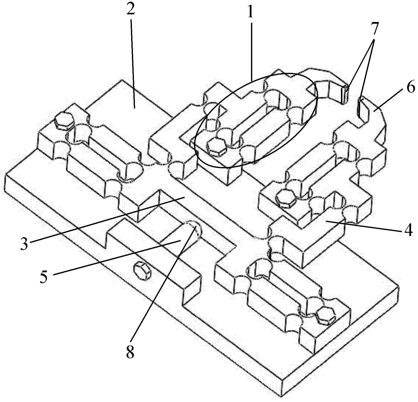
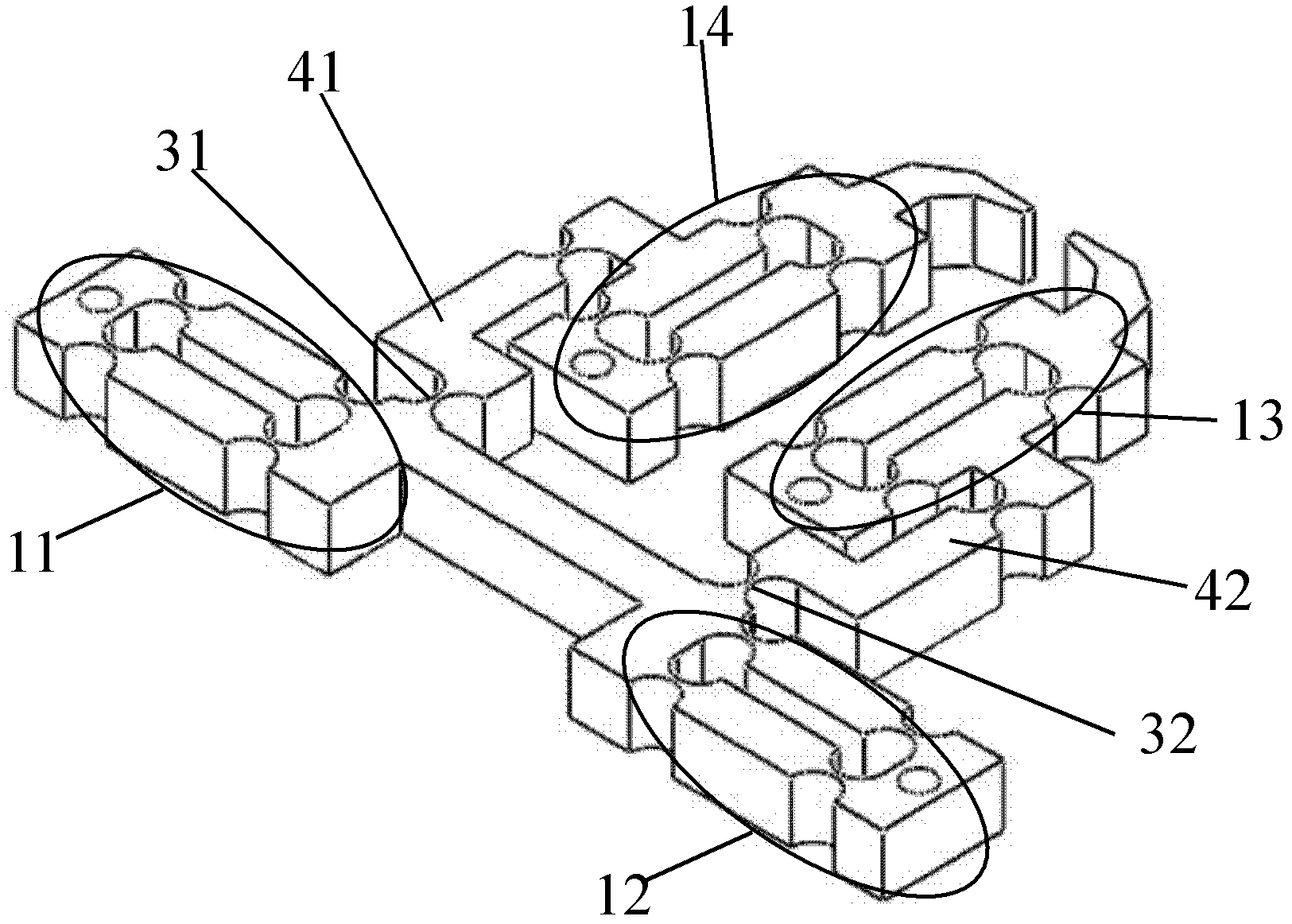
[0019] The two-finger flexible micro-movement gripper (referred to as the gripper, see Figure 1-4 ), mainly including four flexible branch chains with the same structure 1, a base with a boss 2, an "H"-shaped connecting beam 3, a symmetrical "["-shaped connecting beam 41 and a "】"-shaped connecting beam 42. A piezoelectric ceramic driver 5, two "J"-shaped gripping fingers (referred to as gripping fingers) 6, a capacitive displacement sensor 7 and a spherical joint 8;

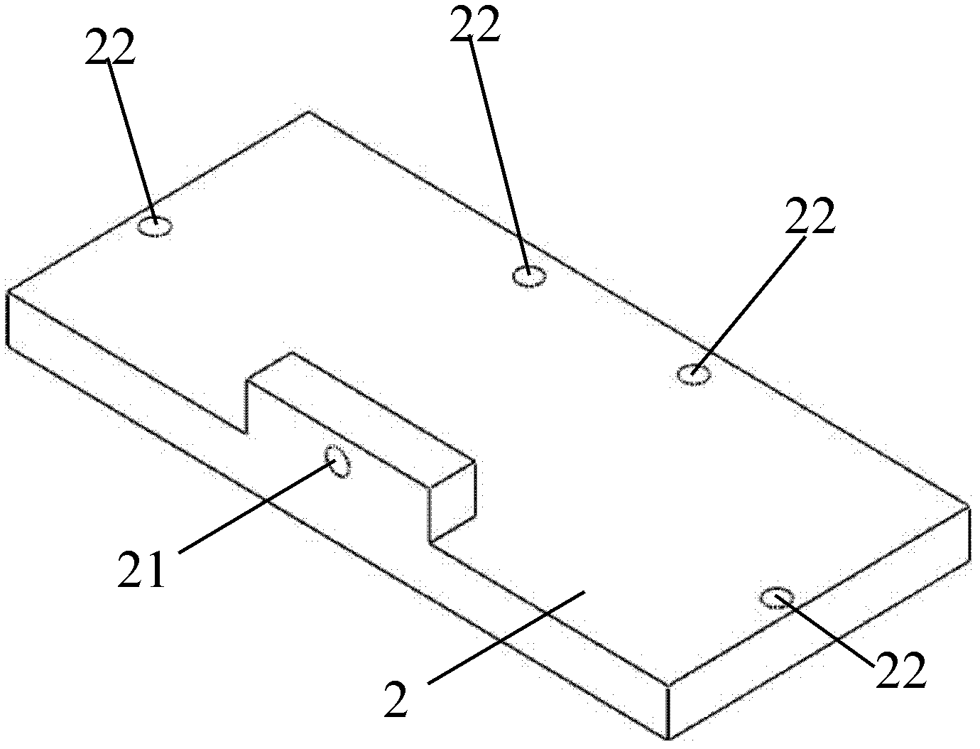
[0020] The embodiment of the base 2 of the present invention is a rectangular plate structure (see image 3 ), there is a boss in the middle of one long side edge, a threaded through hole 21 is opened horizontally in the middle of the boss, and the other three sides have vertical mounting holes 22 (2 on the long side and 2 on the short side). 1 each), the so-called...


PUM


Abstract

The invention discloses a two-finer flexible micro clamper. The clamper is characterized by comprising four flexible branched chains in the same structure, a base, an 'H'-shaped joint beam, a [-shaped joint beam, a ]-shaped joint beam, a piezoelectric actuator, a 'J'-shaped clamping finger, a displacement transducer and a spherical joint, wherein the flexible branched chains are symmetrically arranged on the left and right parts of the base, two flexible branched chains are horizontally arranged and are horizontally connected with the outer side walls of the two '1'-shaped beams at the left end and right end of the 'H'-shaped joint beam, the other two flexible branched chains are vertically arranged and are respectively vertically connected with the upper end faces of the two '1'-shaped beams of the 'H'-shaped joint beam by virtue of the [-shaped joint beam and the ]-shaped joint beam; the spherical joint is arranged at the top end of the piezoelectric actuator, the tail of the piezoelectric actuator is fixed on a boss of the base, the spherical joint props against the middle part of the lower end face of a slotted beam of the 'H'-shaped joint beam, and Hertz contact is realized; and a displacement transducer electrode is arranged at the top end of a hook of the 'J'-shaped clamping finger.

Description

Technical field [0001] The invention relates to a micro operating system in the mechanical field, in particular to a two-finger flexible micro-motion clamp with two clamping ends. Background technique [0002] Micromechanical technology is an important branch of micro-nano technology. Application of scanning probe microscope technology for molecular or atomic-level operations, modification processing, production of micro-mechanical parts and even micro-machines, genetic injection of animal and plant cells in the field of bioengineering, the use of tiny scissors, and micro-cameras in the medical field The realization of micro-traumatic invasive medical operations with special micro-medical devices such as micro-sensors is based on the precision of micro-operating systems or devices. The positioning accuracy of the micro-nano-level operating system is the key to the success of the above-mentioned various micro-operations. With the deepening of people's research on the microscopic...

Claims


Application Information

Patent Timeline
IPC IPC(8): B25J7/00
Inventor 贾晓辉刘今越
Owner HEBEI UNIV OF TECH
Why Eureka
Try Eureka