Supercharge Your Innovation With Domain-Expert AI Agents!

Upper air suction box component of blueprinting machine

A technology of printing machines and suction boxes, applied in optics, instruments, printing equipment, etc., can solve the problems of reducing the speed of printing, inconvenient, waste of human resources, etc., and achieve the effect of increasing the speed of printing

Inactive Publication Date: 2012-01-25
WUXI HENGYUAN OFFICE MACHINERY
View PDF0 Cites 0 Cited by
  • Summary
  • Abstract
  • Description
  • Claims
  • Application Information

AI Technical Summary

Problems solved by technology

In the operation and use of many printing machines, due to the limitation of the mechanical structure, the method of manual paper separation (original manuscript, printed drawing) is usually used. This processing method is inefficient and wastes human resources greatly. Uncertain before and after, after exposure, the direction of the paper is not easy to operate manually, and the speed of printing pictures is reduced, which is very inconvenient

Method used


Image

  • Upper air suction box component of blueprinting machine
  • Upper air suction box component of blueprinting machine
  • Upper air suction box component of blueprinting machine

Examples


Embodiment Construction

[0010] Below the present invention will be further described in conjunction with the embodiment in the accompanying drawing:

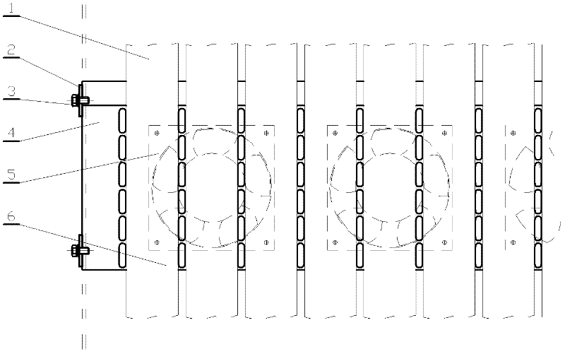
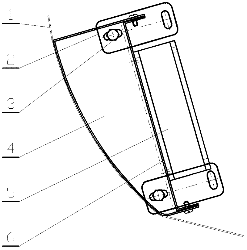
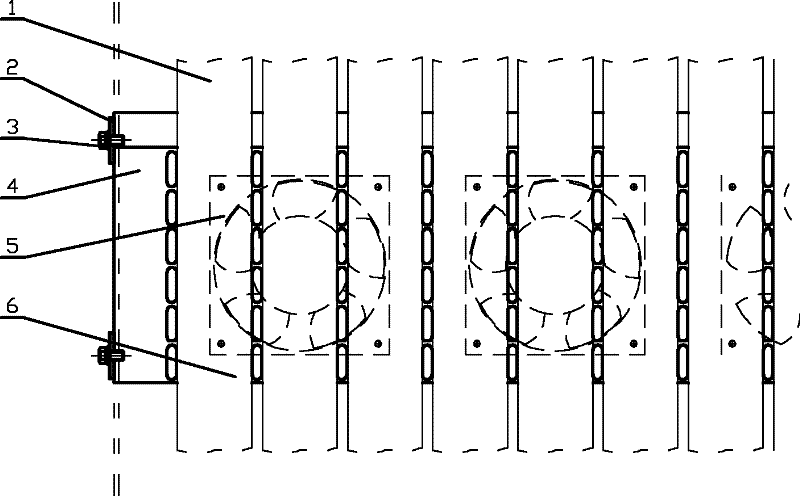
[0011] like Figure 1-2 As shown, it includes a conveyor belt 1, an upper suction box positioning piece 2, a positioning piece fastening screw 3, an upper suction box 4, a suction fan 5, and a suction fan mounting plate 6.

[0012] The upper suction box 4 is positioned on the conveyor belt 1 through the suction box positioning piece 2 and the fastening screw 3, the suction fan mounting plate 6 is installed on the upper suction box 4, and the suction fan 5 is installed on the suction fan mounting plate 6 .

[0013] The relative position of the upper suction box 4 and the conveyor belt 1 is adjusted by the fastening screw 3 and the suction box positioning piece 2 .

[0014] There are two groups of the suction box positioning piece 2 and the fastening screw 3, which are respectively located at the upper and lower ends of the upper suction box 4.

[001...


PUM


Abstract

The invention relates to an upper air suction box component of an ammonia-free blueprinting machine, which belongs to the technical field of office machinery. The component comprises a conveyor belt, an air suction fan, an upper air suction box positioning piece, a positioning piece fastening screw, an upper air suction box and an air suction fan mounting plate, wherein the upper air suction box is positioned on the conveyor belt through the air suction box positioning piece and the fastening screw, the air suction fan mounting plate is arranged on the upper air suction box, and the air suction fan is arranged on the air suction fan mounting plate. After being exposed, the original manuscript of the blueprinting machine and blueprinting paper need to be transmitted separately. The upper air suction box component of the blueprinting machine disclosed by the invention can suck the exposed blueprinting paper so as to transmit the exposed blueprinting paper to a developing mechanism, the troubles of manual paper separation of the exposed original manuscript and blueprinting paper are eliminated, and the blueprinting speed is increased.

Description

technical field [0001] The invention relates to an upper suction box part of an ammonia-free printing machine, specifically an upper suction box part for a 5000PD printing machine, and belongs to the technical field of office machinery. Background technique [0002] In various manufacturing industries and engineering construction, drawings (blueprints) are used in large quantities. In the operation and use of many printing machines, due to the limitation of the mechanical structure, the method of manual paper separation (original manuscript, printed drawing) is usually used. This processing method is inefficient and wastes human resources greatly. It is indeterminate. After exposure, the direction of the paper is not easy to operate manually, which reduces the printing speed, which is very inconvenient. Contents of the invention [0003] The purpose of the present invention is to overcome the deficiencies in the prior art, to provide a suction box part on the non-ammonia ...

Claims


Application Information

Patent Timeline
Patent Type & Authority Applications(China)
IPC IPC(8): G03B27/14
Inventor 刘善虎
Owner WUXI HENGYUAN OFFICE MACHINERY
Features
  • R&D
  • Intellectual Property
  • Life Sciences
  • Materials
  • Tech Scout
  • Unparalleled Data Quality
  • Higher Quality Content
  • 60% Fewer Hallucinations
Learn More