High-efficiency micro-suspension clarification pool

A clarification tank, high-efficiency technology, applied in the direction of sedimentation tank, feeding/discharging device of sedimentation tank, chemical instruments and methods, etc., can solve problems such as unstable effluent water quality, high power consumption of raw water, poor adaptability to changes in treated water volume, etc. , to achieve the effect of convenient operation control and production management

Inactive Publication Date: 2012-02-01
曹玉英
View PDF3 Cites 4 Cited by
  • Summary
  • Abstract
  • Description
  • Claims
  • Application Information

AI Technical Summary

Problems solved by technology

The problems existing in the mechanically stirred clarifier are firstly that the structure is complex, the construction is difficult and the construction cost is high; the second is that the mud content in the circulating sludge is difficult to achieve stable control, which makes the effluent water quality unstable
The problem of the suspension clarifier is that the suspension layer is unstable when the flow rate increases, and the adaptability to the change of the treated water volume is poor; the volume of sludge discharge is large, the scale of sludge discharge water treatment is large, the construction cost is high, and the treatment cost is high
The problem with the water conservancy circulation clarifier is that the negative pressure generated at the bottom of the tank by the jet of raw water sucks the reflux sludge several times larger than the raw water into the throat, so the pressure requirement on the raw water is higher than that of other types of clarifiers, making the raw water high power consumption

Method used


Image

  • High-efficiency micro-suspension clarification pool
  • High-efficiency micro-suspension clarification pool
  • High-efficiency micro-suspension clarification pool

Examples


Embodiment Construction

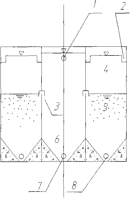
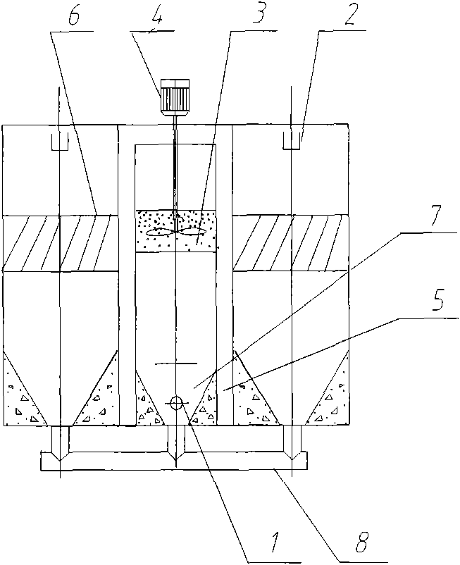
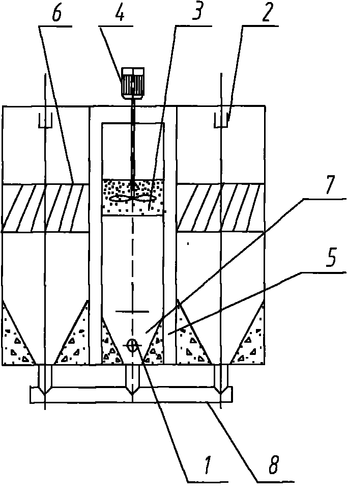
[0011] The water inlet main pipe enters from the middle and lower part of the reaction chamber cone, and the treated water enters the reaction chamber tangentially through the distribution pipe (1). In the middle of the cylindrical section of the reaction chamber, a micro-spin floatation device is set, such as figure 2 The device frame shown in (3) is filled with a rotary float, and the mixer is installed at the position of part number (4) in the figure. After adding the medicine, the raw water flows upward after flocculation reaction in the rotary floating reaction chamber, and overflows into the diversion chamber (5 ), enter the lower part of the clarification chamber through the lower part of the diversion chamber. In the clarification chamber, the water flows from bottom to top, and through the contact and separation of the honeycomb inclined pipe (6), the clean water flows out of the clarification tank through the outlet water distribution tank (2), and the sludge settle...


PUM


Abstract

The invention discloses a high-efficiency micro-suspension clarification pool, and belongs to the technical field of suspension deposition in water treatment. The high-efficiency micro-suspension clarification pool has usually a cylindrical structure. An inner cylinder is a reaction chamber. A middle cylinder is a diversion chamber. An outer cylinder is a clarification chamber. A micro-suspension device is arranged in the reaction chamber and comprises a stirrer capable of producing eddy flows and micro-suspension particles with a function of coagulation aid. Honeycomb-like inclined tubes are installed in the clarification chamber to improve clarification effects. Multiple sludge condensation funnels and a main sludge collecting pipe are installed at bottoms of the reaction chamber and the clarification chamber. Sludge in sludge collecting pipes are discharged periodically from the clarification chamber and simultaneously, clarified water flows out the high-efficiency micro-suspension clarification pool from a water-collecting groove of the clarification chamber, so that raw water clarification treatment is realized. The high-efficiency micro-suspension clarification pool has the advantages that 1, the high-efficiency micro-suspension clarification pool can adapt to water inflow velocity and suspended matter concentration and clarified yield water quality is stable; and 2, sludge water has high sludge content reaching 20 to 30%, and a scale of sludge water treatment equipment and a treatment cost of sludge water are reduced.

Description

Technical field: [0001] The invention relates to a clarification device for water treatment. Background technique: [0002] At present, in water treatment projects, the clarification equipment used for water treatment mainly includes: mechanical acceleration clarifier, suspension clarifier and water conservancy circulation clarifier. Manual Volume 3 - Urban Water Supply, Chapter 7, Section 7.3 Clarification). Their clarification principles are: the mechanical acceleration clarifier is through the action of mechanical stirring, so that the sludge in the first reaction chamber is refluxed and reacts with the raw water after dosing, and continues to react in the second reaction chamber to form larger flocs. particles, and then enter the clarification chamber through the diversion chamber for sedimentation and separation; the suspension clarifier is a sludge suspension contact separation clarifier. The raw water to which the coagulant is added first passes through the air sepa...

Claims


Application Information

Patent Timeline
Patent Type & Authority Applications(China)
IPC IPC(8): B01D21/28B01D21/01B01D21/08B01D21/24
Inventor 曹玉英
Owner 曹玉英
Why Eureka
Try Eureka