Unlock instant, AI-driven research and patent intelligence for your innovation.

Toggle lever clamping unit

A toggle-type and connecting-rod technology, which is applied to presses, manufacturing tools, stamping machines, etc., can solve problems such as inability to uniformly and perfectly select

Active Publication Date: 2012-05-23
KRAUSSMAFFEI TECH GMBH
View PDF4 Cites 24 Cited by
  • Summary
  • Abstract
  • Description
  • Claims
  • Application Information

AI Technical Summary

Problems solved by technology

As a result, the drive design for the crosshead cannot be chosen uniformly and perfectly for both phases or process conditions

Method used


Image

  • Toggle lever clamping unit
  • Toggle lever clamping unit
  • Toggle lever clamping unit

Examples


Embodiment Construction

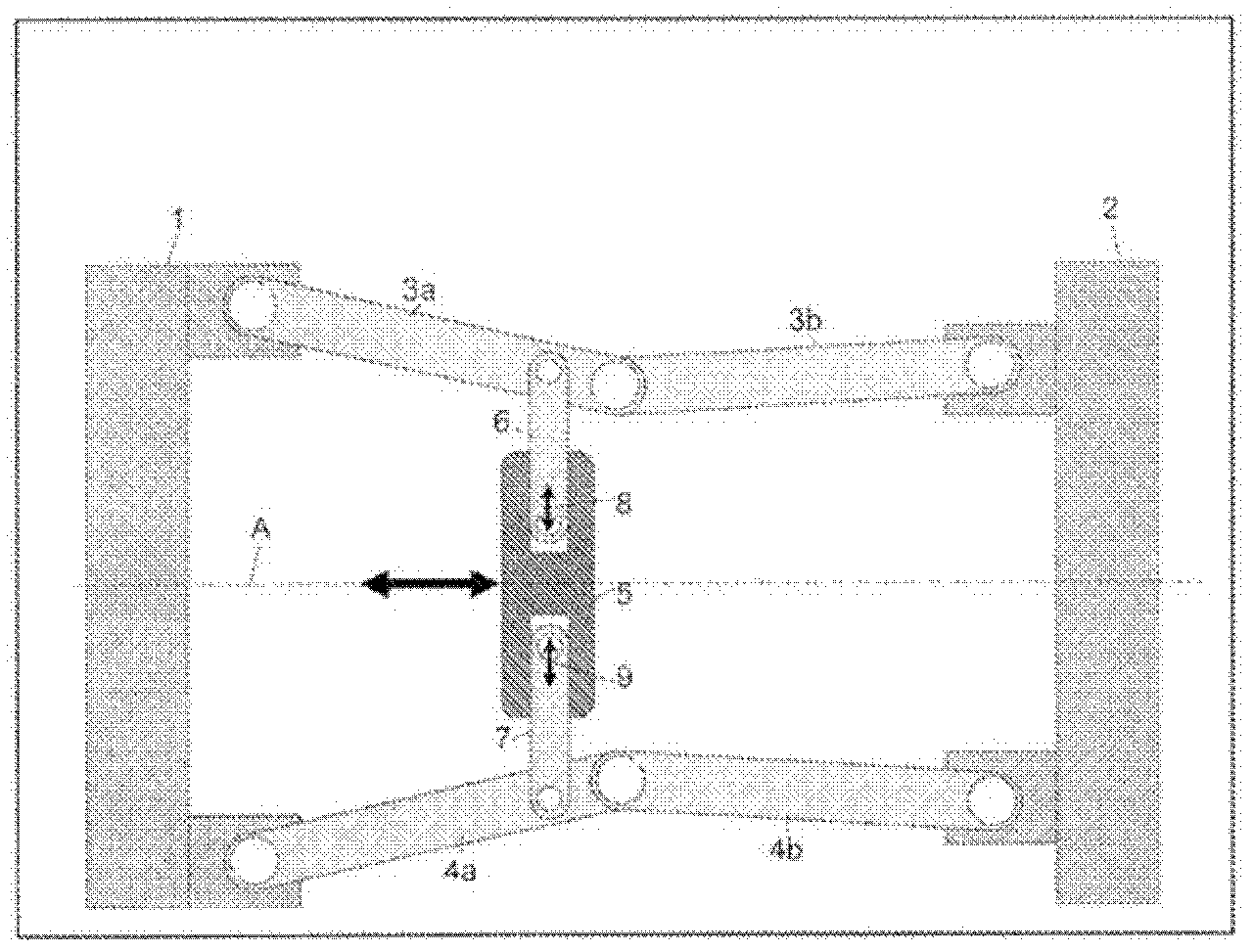
[0011] figure 1 Shown is a schematic view of a part of the toggle clamping unit in the semi-extended state, namely the support plate 1 and the movable mold clamping plate 2 via the force-transmitting lever 3a , 3b and 4a, 4b are hingedly connected to each other at the upper and lower parts. The connecting rods 6 and 7 are articulated on one each of the upper and lower levers, now on said levers 3 a and 4 a , and are connected to the crosshead 5 . As indicated on the axis A by a double arrow, the crosshead 5 is displaceable by means of a drive not shown here along the longitudinal machine axis A, which can also correspond to the injection axis. In or on the crosshead 5 further drive means 8 and 9 are arranged, by means of which the connecting rods 6 and 7 can be moved substantially in a direction perpendicular to the longitudinal axis A of the machine. For example, short-stroke hydraulic cylinders can be arranged in or on the crosshead, wherein the connecting rods 6 and 7 ar...


PUM


Abstract

The invention relates to a toggle lever clamping unit for an injection molding machine, wherein the cross clamp (5) can be linearly moved along the longitudinal axis (A) of the machine by way of a first drive (30, 40). In order to be able to downsize said drive, according to the invention, one or several additional drives (8, 9) are provided between the cross clamp (5) and the primary levers (3a, 3b; 4a, 4b), which drives are operationally connected to the connecting levers (6, 7). By way of said drives, the connecting levers (6, 7) can be moved essentially in a direction that is orthogonal to the longitudinal axis of the machine (A) relative to the cross clamp (5) and / or relative to the primary levers (3a, 3b; 4a, 4b), in order to make it possible to put the primary levers (3a, 3b; 4a, 4b) in the fully extended position, and / or that length-adjustable connection levers (6', 7') are provided between the primary levers (3a, 3b; 4a, 4b) and the cross clamp (5), wherein for each of the connecting levers (6', 7'), at least one additional drive (20, 21) is provided, with which the length of the respective connecting lever (6', 7') can be adjusted in order to make it possible to put the primary levers (3a, 3b; 4a, 4b) in the fully extended position.

Description

technical field [0001] The invention relates to a toggle clamping unit for an injection molding machine according to the preamble of claim 1 . Background technique [0002] Knuckle-joint clamping units of this type, which are embodied in various ways, are known in the prior art. In principle, the linear movement of the so-called crosshead is effected by means of a hydraulic or electric drive. The crosshead functions as a central hinge point and as a drive point for the force-transmitting lever pair of the toggle mechanism between the carrier plate of the clamping unit and the movable mold clamping plate. The linear movement of the crosshead is converted into the rotational movement of the force-transmitting lever pair by means of a connecting rod adapted to the force-transmitting lever pair, so that the lever pair repeats between an inwardly folded state and an extended state. Moved, the inwardly folded state corresponds to an open clamping unit, and the extended state cor...

Claims


Application Information

Patent Timeline
IPC IPC(8): B29C45/66B29C45/68B30B15/14B30B1/16
CPCB29C45/681B30B1/14B29C45/661B30B1/16
Inventor D·阿默尔G·克拉比希勒
Owner KRAUSSMAFFEI TECH GMBH