Method for effectively realizing time-code signal receiving of indoor electric waves

A time code signal and radio wave technology, which is applied to effectively solve the field of indoor radio time code signal reception, can solve the problems of reception failure, cluttered electromagnetic wave radiation, interference, etc., and achieve the effect of improving the success rate

Active Publication Date: 2014-07-02
FUZHOU YIMEI ELECTRONICS
View PDF5 Cites 0 Cited by
  • Summary
  • Abstract
  • Description
  • Claims
  • Application Information

AI Technical Summary

Problems solved by technology

[0006] Due to the use of a large number of electrical and electronic equipment indoors in daily life, relatively messy electromagnetic wave radiation is generated, and the radio clock receiving technology is a low-frequency electromagnetic wave receiving technology, which is easily interfered by electromagnetic waves generated by indoor electrical and electronic equipment, causing reception fail

Method used


Image

  • Method for effectively realizing time-code signal receiving of indoor electric waves
  • Method for effectively realizing time-code signal receiving of indoor electric waves

Examples


specific Embodiment approach

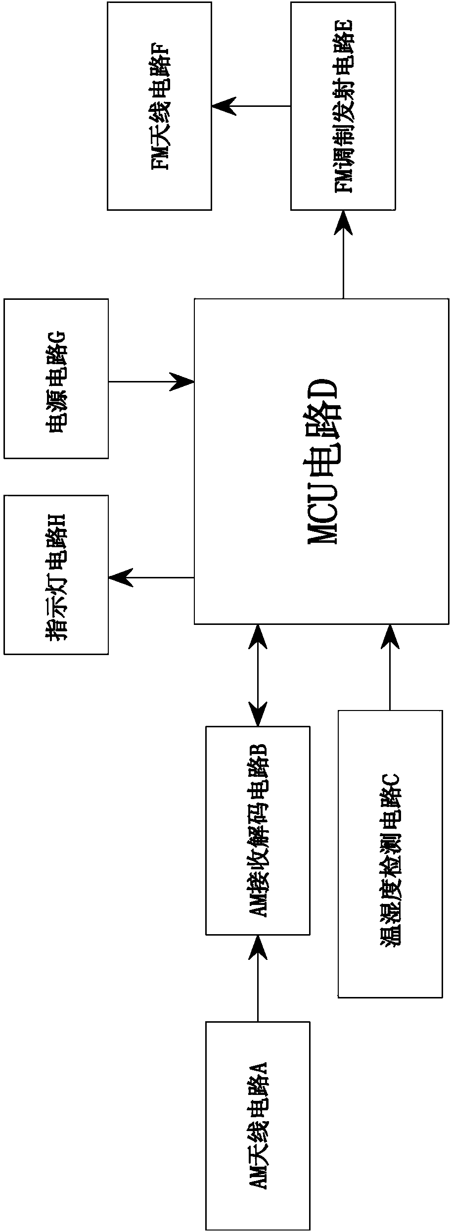
[0024] Such as figure 1 , figure 2 As shown, a method for effectively solving indoor radio time code signal reception is characterized in that it includes a transmitting circuit board including AM antenna circuit A, AM receiving and decoding circuit B, temperature and humidity detection circuit C, MCU circuit D, and FM modulation transmission Circuit E, FM antenna circuit F, power supply circuit G, indicator light circuit H, wherein:

[0025] (1), described MCU circuit D sends the radio wave clock to receive instruction, stimulates the AM receiving decoding circuit B in dormant state, receives the timing electromagnetic wave signal that the time service center transmits through AM antenna circuit A, is amplified and decomposed by AM receiving decoding circuit B After the adjustment, after outputting the distinguishable signal of the MCU circuit D, perform software analysis, read the timing information, and adjust the time of the device. At the same time as receiving the sign...


PUM


Abstract

The invention discloses a method for effectively realizing time-code signal receiving of indoor electric waves. The method is characterized in that a transmitting circuit board comprises an AM (Amplitude Module) antenna circuit, an AM receiving and decoding circuit, an MCU (Micro Control Unit) circuit and an indicating lamp circuit, wherein the MCU circuit sends an instruction received by an electric wave clock, and excites the AM receiving and decoding circuit; a timing electromagnetic wave signal transmitted by a time service center is received by the AM antenna circuit; after amplification and demodulation of the AM receiving and decoding circuit, the MCU circuit reads timing time information and carries out timing adjustment on the time; when receiving the signal, the MCU circuit sends an instruction to the indicating lamp circuit and prompting that the signal is being received; and after the receiving is successful, the MCU circuit sends an interruption request signal, prompts that the decoding is finished, sends a receiving stopping instruction to the AM receiving and decoding circuit, so that the AM receiving and decoding circuit returns to a sleeping state and simultaneously the indicating lamp circuit is stopped. The method has the advantages that the structure is simple, the operation is simple and convenient and the outdoor temperature detection can be realized.

Description

technical field [0001] The invention relates to the field of wireless transmitters, in particular to a method for effectively solving indoor radio wave time code signal reception. Background technique [0002] The principle of radio time calibration: it can receive time calibration signals containing standard time data, and adjust its current time accordingly. The whole system consists of two parts: 1: The transmitting end refers to the long-wave signal transmitting tower, which contains an atomic clock, and the time is accurate to 100,000 years with an error of no more than 1 second. The location is fixed, and it transmits to a radius of 1000 kilometers to 2000 kilometers; 2: The receiving end refers to radio-controlled clocks and watches, which contain long-wave receiving antennas. The receiving process is: 1. Use the built-in antenna to receive the signal, 2. The receiving end decodes the received data and converts it into time data. 3. The receiver adjusts the time acc...

Claims


Application Information

Patent Timeline
Patent Type & Authority Patents(China)
IPC IPC(8): H04B1/16
Inventor 陈祖元黄华剑
Owner FUZHOU YIMEI ELECTRONICS
Why Eureka
Try Eureka