Distributed power supply system of relay protection device

A technology of relay protection device and power supply system, applied in the direction of emergency power supply protection, etc., can solve the problems of increasingly high requirements, long development cycle, and partial influence of double plug-in sampling

Active Publication Date: 2012-07-18
BEIJING SIFANG JIBAO AUTOMATION +1
View PDF4 Cites 12 Cited by
  • Summary
  • Abstract
  • Description
  • Claims
  • Application Information

AI Technical Summary

Problems solved by technology

[0004] 1. There are many output channels and voltage levels of the power supply, the output voltages of each channel need to be isolated, the design is complicated, and the overall reliability of the power supply is reduced
[0005] 2. There are many output channels of the power supply, the internal inherent power loss remains high, the heat of the power plug-in part is concentrated, and the working temperature rises
[0006] 3. The power supply has many output voltage circuits, multiple voltage levels, poor design reusability, high frequency of customized development, and long product development cycle
[0008] 5. The power supply part of each functional plug-in is directly connected. When a power supply fails, it may cause abnormal operation of all plug-ins. In severe cases, it may cause abnormal operation of the device or even malfunction.
For example, when there are two CPU plug-ins, if there is a problem with the power supply system of the analog circuit, the sampling part of the dual plug-ins will be affected, and the sampling will be abnormal.
[0009] 6. With the increase of device functions, especially the number of optical fiber communication interfaces required in the intelligent station is very large, the requirements for the power supply of the 5V digital part of the device are getting higher and higher, and some peak power has exceeded 50W
In this way, the current exceeding 10A must be transmitted on the backplane power bus, and the influence of voltage drop and contact resistance on the power bus has to be considered, and the design efficiency of the entire system is low;
[0010] 7. Due to the large number of power output channels, the power of some circuits is relatively large, and the number of pins on the backplane bus occupied by the power supply part is large, which affects the overall design of the device and is susceptible to interference

Method used


Image

  • Distributed power supply system of relay protection device
  • Distributed power supply system of relay protection device
  • Distributed power supply system of relay protection device

Examples


Embodiment Construction

[0029] The technical solution of the present invention will be described in further detail below according to the accompanying drawings.

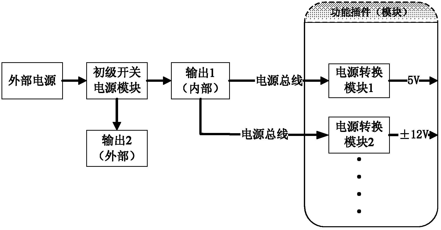
[0030] The invention discloses a distributed power supply system for a relay protection device. The power supply system includes a primary power supply module, a power bus, and a power conversion module. The system is constituted as follows: figure 1 shown.

[0031] The primary power module converts the external input voltage into the required power supply inside the device; in order to improve the power conversion efficiency, the primary power module is designed as a switch type, and its input voltage can be DC220V, DC110V, DC48V and other DC voltages, It can also be an AC voltage. The input end of the module is externally connected to an external power supply, and two mutually isolated power outputs are designed internally, both of which are 24VDC; among them, the first output is introduced into the power bus, and output to each function...


PUM


Abstract

The invention discloses a distributed power supply system of a relay protection device. In the power supply system, a primary power source module is designed with two paths of separated 24V DC voltage outputs, wherein one path of output is used for internal power supply and the other path of output is used for external power supply. The path of output used for internal power supply is output to each functional insert (module) via a power source bus, and then the internal 24V DC is converted to be at a voltage level needed by the functional module via a secondary power source conversion module. Through the distributed power supply system of the relay protection device, some problems of a centralized power supply are effectively solved; the design complexity of the primary power source module is simplified and the reliability and the design reusability of the power supply are improved; and meanwhile, the backplane resource of the relay protection device is saved and the development cycle of the product is shortened.

Description

technical field [0001] The invention belongs to the field of relay protection of power systems, and specifically relates to a brand-new power supply system for relay protection devices, which can be widely used in various relay protection devices of power systems, and can also be extended to power supply schemes for other types of equipment in the field of power systems . Background technique [0002] In the power system relay protection devices, centralized power supply is currently used; that is, an independent power plug-in (or module) is used to convert external 48VDC, 110VDC, 220VDC or even AC into 5V, ±12( 15) V and 24V, and then lead these output power sources to use on each functional plug-in (module) through the backplane bus or power line. On each functional plug-in, only when using a power supply other than the above voltage levels, such as 3.3V, the DC / DC module conversion mode is used. [0003] The current centralized power supply method has the following tech...

Claims


Application Information

Patent Timeline
Patent Type & Authority Applications(China)
IPC IPC(8): H02H1/06
Inventor 徐刚张涛暴立勇
Owner BEIJING SIFANG JIBAO AUTOMATION
Why Eureka
Try Eureka