Controlled-silicon adapting LED (light-emitting diode) driving circuit, method and switch power supply

A technology of LED driving and switching power supply, which is applied in the direction of electric light source, electroluminescent light source, electric lamp circuit layout, etc., which can solve the problems of noise emission, irregular restart of thyristor, and different power, so as to avoid flicker and noise effect

Active Publication Date: 2012-12-26
SILERGY SEMICON TECH (HANGZHOU) CO LTD
View PDF5 Cites 60 Cited by
  • Summary
  • Abstract
  • Description
  • Claims
  • Application Information

AI Technical Summary

Problems solved by technology

[0003] The LED driving circuit with thyristor in the prior art generally controls the switching action of the power switch tube in the power stage circuit to provide a constant output current for the LED lamp load, and its driving circuit is often equipped with a power factor correction function. Therefore, the input voltage and input current waveforms of its power stage circuit remain consistent, such as figure 1 Shown is the input voltage and input current waveform diagram of the LED drive circuit with thyristor in the prior art. In the LED drive circuit with thyristor in the prior art, the shutdown of the thyristor is generally When the input current of the power stage circuit is less than the holding current of the thyristor, the thyristor is naturally turned off. At this time, since the input voltage has not dropped to zero, the thyristor trigger circuit will be charged to turn on the thyristor again. At this time, the input current may generate as figure 1 The oscillation shown in the figure then causes multiple irregular restarts of the thyristor, which makes the power absorbed by the LED drive circuit from the input side different in each cycle, resulting in different brightness of the LED lamp load in different cycles , causing the LED to strobe and possibly noisy

Method used


Image

  • Controlled-silicon adapting LED (light-emitting diode) driving circuit, method and switch power supply
  • Controlled-silicon adapting LED (light-emitting diode) driving circuit, method and switch power supply
  • Controlled-silicon adapting LED (light-emitting diode) driving circuit, method and switch power supply

Examples


Embodiment Construction

[0033] Several preferred embodiments of the present invention will be described in detail below with reference to the accompanying drawings, but the present invention is not limited to these embodiments. The present invention covers any alternatives, modifications, equivalent methods and solutions made on the essence and scope of the present invention. In order for the public to have a thorough understanding of the present invention, specific details are described in the following preferred embodiments of the present invention, and those skilled in the art can fully understand the present invention without the description of these details.

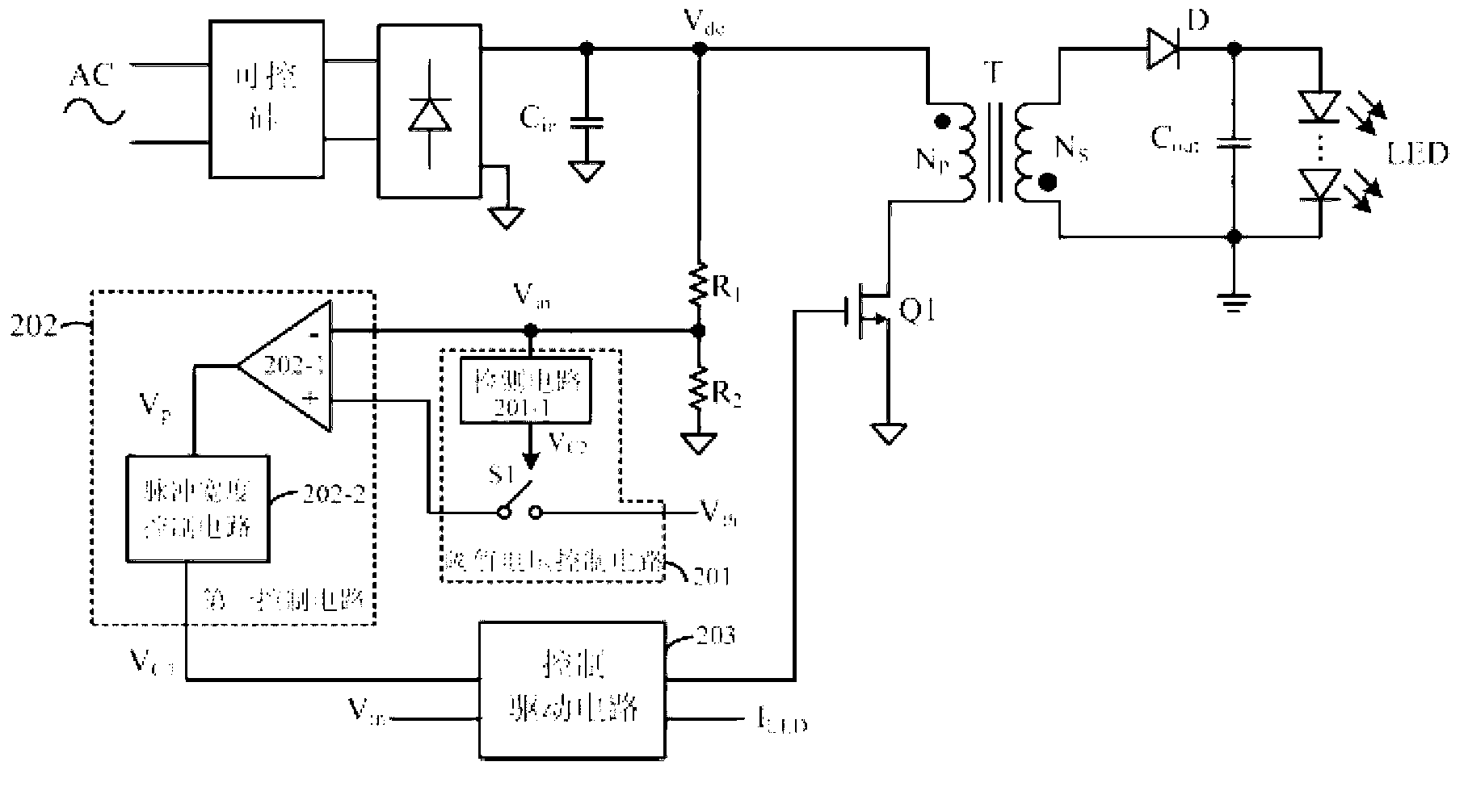
[0034] Referring to FIG. 2, there is shown a circuit diagram of an LED drive circuit adapted to thyristor according to the present invention. The LED drive circuit of the present invention is applied to a switching power supply by controlling the power switch in the switching power supply. Switch action to convert the AC voltage of the grid i...


PUM


Abstract

The invention discloses a controlled-silicon adapting LED (light-emitting diode) driving circuit, method and switch power supply. The input voltage signal of the representing sine half-wave voltage signal is compared with a threshold voltage to obtain a first comparison pulse signal, and then the effective width of the first comparison pulse signal is extended for a period of time to obtain a first control signal, wherein the first control signal controls a power switch tube switches off before the input current is reduced to be equal to the maintenance current of a controlled silicon, and the power switch tube switching-off state is made to last for a period of time to the next cycle, so that the load current of the controlled silicon is made to be larger than the maintenance current all the way in the conducting time interval of the controlled silicon, the controlled silicon does not need to be re-conducted irregularly for many times, the input power of the system in each half cycle is same, and LED lamp is prevented from flicking under load and generating noise.

Description

Technical field [0001] The invention relates to the field of switching power supplies, and more specifically, to an LED driving circuit, a driving method and a switching power supply using the same. Background technique [0002] Light-emitting diodes (LED) are widely used in offices, homes and other occasions due to their high efficiency and energy saving. Now LED lighting has become the mainstream technology in the lighting field. However, how to replace the existing incandescent lighting with LED lighting? It is a key issue that needs to be solved urgently to properly match the LED lamp with the thyristor dimmer in the traditional circuit to achieve precise dimming. [0003] The LED drive circuit with thyristor in the prior art generally controls the switching action of the power switch tube in the power stage circuit to provide a constant output current for the LED lamp load. The drive circuit often has a power factor correction function. Therefore, the input voltage and input ...

Claims


Application Information

Patent Timeline
Patent Type & Authority Applications(China)
IPC IPC(8): H05B37/02H02M3/335H05B44/00
CPCY02B20/346H05B33/0851H05B33/0815Y02B20/348H05B45/10Y02B20/30H05B45/3725H05B45/385
Inventor 余峰黄晓冬
Owner SILERGY SEMICON TECH (HANGZHOU) CO LTD
Why Eureka
Try Eureka