A multi-rotor upright vehicle

An aircraft and multi-rotor technology, applied in the field of aircraft, can solve the problems of small load, high maintenance cost, and easy loss of control, and achieve the effects of reducing the speed of descent, improving wind resistance, and improving stability

Pending Publication Date: 2018-12-21
汉中天行智能飞行器有限责任公司
View PDF0 Cites 2 Cited by
  • Summary
  • Abstract
  • Description
  • Claims
  • Application Information

AI Technical Summary

Problems solved by technology

[0002] Most of the existing multi-rotor aircraft are driven by electric motors, which results in a short flight time and light load. Some multi-rotor aircraft are driven by engines, but these multi-rotor aircraft are complex in structure, and they all adopt the pitch control method. In one body, the control is complicated, the failure rate is high, the reliability is poor, and the maintenance cost is high in the later stage; secondly, there is no safety protection device on the multi-rotor aircraft. Once the aircraft loses control and falls, it will not only cause losses but also cause harm; When flying, it is inconvenient to control the direction, and it is not stable enough when turning the direction, and there is a hidden danger of easy loss of control

Method used


Image

  • A multi-rotor upright vehicle
  • A multi-rotor upright vehicle
  • A multi-rotor upright vehicle

Examples


Embodiment 1

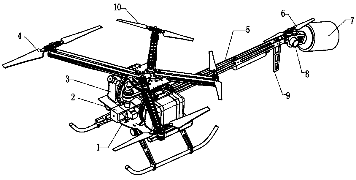
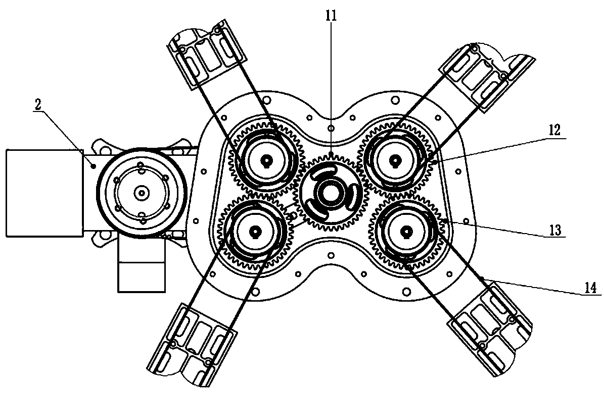
[0027] As shown in the figure, the present invention is a multi-rotor helicopter. , comprising a frame 1, a driving device, a transmission mechanism, a rotor bracket, a plurality of rotors, an empennage 5, a synchronizer, a protection device 7, a direction control device and a controller, the rotor bracket is arranged on the frame 1, and the plurality of rotors Set on the rotor bracket, the empennage 5 is connected with the frame 1; the driving device, controller and synchronizer are all arranged in the frame 1, the synchronizer is connected with the driving device, and the synchronizer is connected with multiple The branch rotors are connected; the empennage 5 is provided with a direction control device and a protection device 7; the controller is connected with the drive device and the protection device 7 respectively, and a synchronizer is used to control the drive device to drive the multi-rotors to rotate, so that the symmetrical rotors have the same The rotating speed an...

Embodiment 2

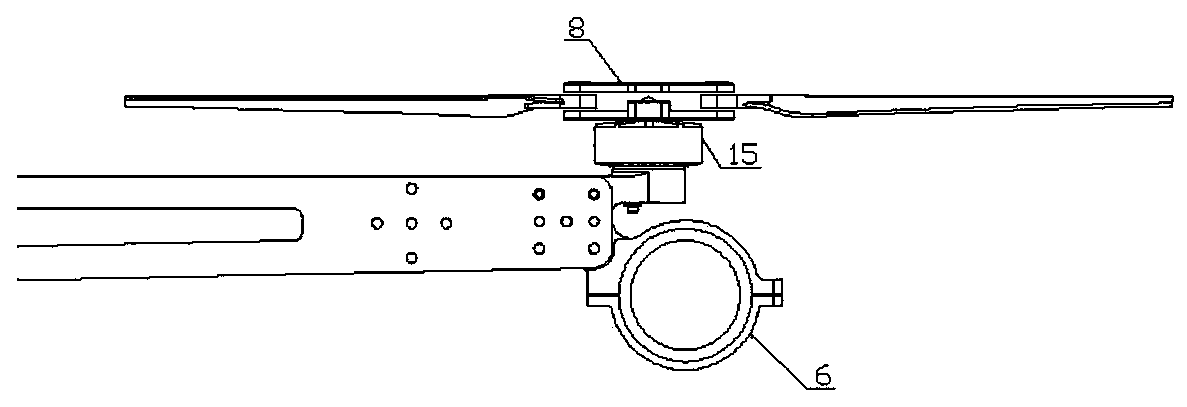
[0037] This embodiment is basically the same as Embodiment 1, the difference is that the direction control device also includes motors 15 arranged symmetrically up and down, and the motors 15 are respectively connected with propellers 6, and the central axes of the propellers 6 are all located on the same vertical plane. Inside. One of the motors 15 is forward rotation, and the other is reverse rotation. The two propellers 6 of the guiding device have a speed difference when they rotate. When controlling the guiding like this, compared with embodiment 1, the safety can be improved.


PUM


Abstract

The invention relates to the technical field of aircraft, in particular to a multi-rotor upright aircraft. Comprises a frame, a driving device, a transmission mechanism, a rotor bracket, a plurality of rotors, a tail wing, a synchronizer, a protection device, a direction control device and a controller, wherein the rotor bracket is arranged on the frame, the plurality of rotors are arranged on therotor bracket, and the tail wing is connected with the frame; The driving device, the controller and the synchronizer are all arranged in the frame, the synchronizer is connected with the driving device, and the synchronizer is connected with a plurality of rotors through the driving mechanism; Adopt engine instead of electric motor to drive rotor, improve all-weather long-distance service ability; The synchronizer technology is used to drive the multi-rotor to rotate, so that the symmetrical rotor has the same rotational speed and input power, which ensures the symmetrical lift force. The automatic longitudinal and lateral trimming technology of aircraft uses a tail motor to achieve tilting and rotational speed changes, and to carry out longitudinal and lateral trimming of aircraft, thusachieving stable flight.

Description

technical field [0001] The invention relates to the technical field of aircraft, in particular to a multi-rotor helicopter aircraft. Background technique [0002] Most of the existing multi-rotor aircraft are driven by electric motors, which results in short flight time and light load. Some multi-rotor aircraft are driven by engines, but these multi-rotor aircraft are complex in structure, and they all adopt the pitch control method. The control and execution are integrated. In one body, the control is complicated, the failure rate is high, the reliability is poor, and the maintenance cost is high in the later period; secondly, there is no safety protection device on the multi-rotor aircraft. Once the aircraft loses control and falls, it will not only cause losses but also cause harm; When flying, it is inconvenient to control the direction, and it is not stable enough when turning the direction, and there is a hidden danger of easy loss of control. Contents of the inventi...

Claims


Application Information

Patent Timeline
Patent Type & Authority Applications(China)
IPC IPC(8): B64C27/08B64D27/08B64D35/04B64C19/02B64D45/00B64C1/00B64C11/20
CPCB64C27/08B64C1/0009B64C11/20B64C19/02B64D27/08B64D35/04B64D45/00
Inventor 丁重舜王俊王斌贾小强张澄宇祖宁军张西平
Owner 汉中天行智能飞行器有限责任公司
Why Eureka
Try Eureka