Dynamic control method of temperature in the central area of ​​array LED lighting fixtures

A technology for LED lighting and the central area, which is applied in lighting devices, energy-saving control technology, lamp circuit layout, etc., can solve the problems of overheating, complex mechanical structure, and temperature drop in the central area of ​​LED lighting lamps, so as to avoid poor heat transfer, Improve luminous efficiency and reduce heat loss

Inactive Publication Date: 2014-10-29
SOUTHEAST UNIV
View PDF7 Cites 0 Cited by
  • Summary
  • Abstract
  • Description
  • Claims
  • Application Information

AI Technical Summary

Problems solved by technology

[0010] The purpose of the present invention is to solve the problem of overheating in the central area of ​​LED lighting fixtures, and at the same time overcome the shortcomings of traditional cooling methods such as complex mechanical structures, increased energy consumption, and the need for external temperature sensors, and propose a method of dynamically controlling LED lighting with different duty ratios. The method of turning on and off the LED light-emitting tubes in the middle area of ​​the lamp realizes the temperature control of the high-temperature area of ​​the LED light-emitting tube array, and significantly reduces the temperature in the central area of ​​the LED light-emitting tube array while minimizing the overall brightness of the lamp.

Method used


Image

  • Dynamic control method of temperature in the central area of ​​array LED lighting fixtures
  • Dynamic control method of temperature in the central area of ​​array LED lighting fixtures
  • Dynamic control method of temperature in the central area of ​​array LED lighting fixtures

Examples


Embodiment Construction

[0033] The present invention will be further described below in conjunction with the drawings and specific embodiments.

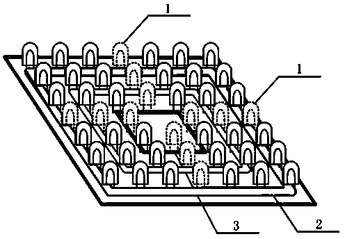
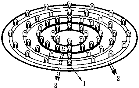
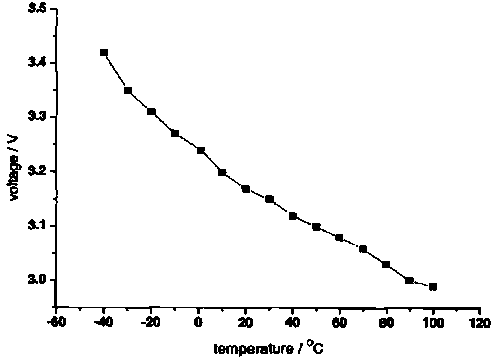
[0034] Implementation example figure 1 , figure 2 , image 3 , Figure 4 with Figure 5 As shown, the embodiment provides a method for dynamically controlling the temperature in the central area of ​​the array LED lighting fixture. The control object is the different level areas in the center of the LED luminous tube array where the LED lighting lamps heat seriously. Such as figure 1 with figure 2 As shown, the temperature detection method is to obtain each temperature measurement LED light-emitting tube 1 ( figure 1 , figure 2 The PN junction voltage drop of the dotted line LED light-emitting tube in the middle row, using such as image 3 The pressure drop of the PN junction shown is approximately linearly decreasing with the increase of temperature, and the temperature of each level of the LED light-emitting tube in the LED light-emitting tube array (i...


PUM


Abstract

The invention discloses a method for dynamically controlling temperature of a central area of an array light emitting diode (LED) lighting lamp. According to the method, a characteristic that forward voltage drop of a positive-negative (PN) junction of an LED luminescent tube declines linearly along with the increasing of the temperature is utilized to detect the temperature of an LED lighting array; after a microprocessor acquires the temperature of each area, the on-time of the LED luminescent tubes on each level in the center area of an LED luminescent tube array are regulated in a pulse width modulation (PWM) way, and the average working current of the LED luminescent tubes is regulated, so that the temperature of the LEDs in different level areas in the center can be dynamically controlled, and the temperature is maintained in a range of (120+ / -5) percent of the temperature of LED lamps in an utmost periphery low-temperature area. By the method, under the condition that overall luminance is not influenced basically, the temperature of the center area of the LED luminescent tube array can be effectively reduced, the luminous efficiency of the LED luminescent tubes can be improved, the power consumption of the LED lamps can be reduced, and the service lives of the LED luminescent tubes in the center area and the whole LED lamp can be prolonged.

Description

Technical field [0001] The invention relates to a method for dynamically controlling the temperature in the central area of ​​an array type LED lighting lamp, which belongs to the technical field of LED lighting. Background technique [0002] LED lighting is a lighting technology that has developed rapidly in recent years. Compared with traditional lighting sources, LED lighting technology has the advantages of low working voltage, low power consumption, high luminous efficiency, and long life. The existing LED lighting fixtures can save more than 80% of electricity than incandescent lamps and more than 50% of fluorescent energy-saving lamps. Under the background of national energy saving and emission reduction, the low energy consumption characteristics of LED lighting will surely make it become the mainstream of lighting technology development, and there will be broad development space in the lighting market in my country. [0003] Most of the LED luminous tubes are small...

Claims


Application Information

Patent Timeline
Patent Type & Authority Patents(China)
IPC IPC(8): H05B37/02
CPCY02B20/42Y02B20/40
Inventor 周杏鹏孙凯王袆
Owner SOUTHEAST UNIV
Why Eureka
Try Eureka